


HUMIDIFICATION DEVICES
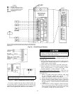
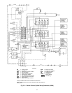
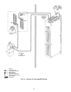
Modulating Valve for Analog Output Humidity Control
(Fig. 55) — Valve selected must be able to receivea4to
20 mAsignal and must NOT exceed an impedance of 600 ohms.
Valve power supply must be field-installed and isolated.
Install valve on humidifier piping and connect actuator power
supply. Using a 20 AWG twisted wire pair, connect the posi-
tive (ϩ) contact of the valve actuator to pin 40 of the option
module. Connect the negative (−) contact of the valve ac-
tuator to pin 41 of the option module.
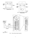
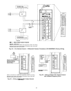
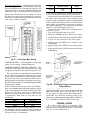
Two-Stage Humidification Control Relays — Two SPDT
relays with silver cadmium contacts are shipped with the unit
when 2-stage humidification control is requested. See
Fig. 52. The relays are rated as follows:
48 va at 24 vac and .25 power factor
125 va at 115 vac and .25 power factor
125 va at 230 vac and .25 power factor
The relays must be field installed within a field-supplied en-
closure rated for the application.
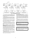
Wire the stage 1 relay as follows: Connect the 24 vac coil
contacts 1 and 2 to pins 41 and 42 of the option module. The
stage 1 relay is intended to open a normally-closed steam
valve and not energize the spray pump. See Fig. 56 for field
wiring of the stage 1 valve and steam pump.
Wire the stage 2 relay as follows: Connect the 24 vac coil
contacts 1 and 2 to pins 44 and 45 of the option module. The
stage 2 relay is intended to open a second normally-closed
steam valve. See Fig. 56 for field wiring of the stage 2 valve.
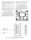
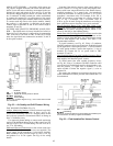
Duct High Humidity Switch — The humidistat is factory sup-
plied and field installed. It is shipped (with a template) in its
own box.
All wiring must comply with applicable local codes and
ordinances. Wire the DHH as follows:
1. Turn switch on PIC control box to OFF.
Turn switch on PIC control box to OFF before con-
necting DHH wiring, otherwise electrical shock or
equipment damage can result.
2. Connect wire from terminal 3 of terminal block 2 (TB2)
to the terminal labeled ORANGE on the DHH sensor. See
Fig. 57.
3. Connect wire from pin 7 of the option module to the sen-
sor screw terminal labelled RED.
During humidification, the duct high humidity switch must
be set to the maximum humidity level desired in the supply
duct (80% minimum).
Duct Mounted/Wall Mounted Relative Humidity Transmit-
ter (Fig. 58) — Identify the power terminal block (ACIN)
and signal terminal block (OUT). See Fig. 59 and 60. Using
20 AWG twisted wire pair, connect the 24 vac power to the
terminal labeled ACIN.
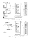
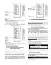
Field Wiring
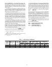
NOTE: The relay furnished is a SPDT relay with silver cadmium ox-
ide contacts, rated as follows:
48 va at 24 vac and .25 power factor
125 va at 115 vac and .25 power factor
125 va at 230 vac and .25 power factor
Fig. 53 — Wiring of Device Under Discrete Output
Temperature Control
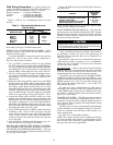
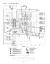
Field Wiring
NOTE: The relay furnished is a SPDT relay with silver cadmium ox-
ide contacts, rated as follows:
48 va at 24 vac and .25 power factor
125 va at 115 vac and .25 power factor
125 va at 230 vac and .25 power factor
Fig. 54 — Wiring of Discrete Output Device
Under Timeclock Control
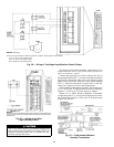
Field Wiring
Fig. 55 — Wiring of the Modulating Valve for
Analog Output Humidity Control
59