


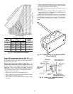
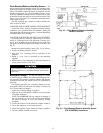
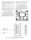

OAC CALIBRATION — Once the probe and tubing are in-
stalled, input the set point to match the probe readings. Be-
fore adjusting the OAVP probe, ensure that the supply-air
fan is providing the maximum design airflow and that the
outside-air dampers are adjusted for the design outdoor
airflow intake.
To calibrate the PIC processor to match the probe loca-
tion, use a precision manometer to measure the velocity pres-
sure in the outdoor air duct at design conditions. Use the
HSIO (local interface device) or Building Supervisor to in-
put the value as the OAVP set point.
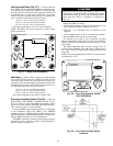
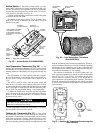
Note that the probe does not measure true velocity pres-
sure; when positioned as recommended, the probe measures
a velocity pressure 1.563 times that of the velocity pressure
in the duct. This multiplier (magnification) factor varies with
the probe’s location, and can even be negative if the probe
is located at an elbow or turn. All OAVP values displayed on
the HSIO incorporate the multiplier factor to show the true
duct velocity pressure.
If a precision manometer is not available, read the veloc-
ity pressure value at the HSIO when the system is running
at maximum design airflow and input that value as the set
point. During normal operation, the velocity pressure is held
constant as the supply fan modulates.
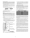
USING OAVP VALUES TO DETERMINE DUCT AIR-
FLOW — It is possible to determine the airflow (cfm) in the
outside air duct based on the readings obtained by the OAVP
probe. See the following procedure.
Use the HSIO and status function ( ) to display
the outside air velocity pressure (Pv) at the transducer.
Find the average velocity (V) in the duct, in fpm:
4005
͌ʲʲPv = V
Obtain the cross-sectional area of the duct in sq ft. (A). To
determine the airflow (F) in the duct, in cfm:
VxA=F
If the airflow obtained by the preceding method is differ-
ent from the design airflow or a measurement obtained with
a balancer, the OAVP probe is not sensing the average duct
velocity and/or the probe’s multiplier factor is effectively not
1.563. To match the design or measured airflow to the air-
flow determined with the preceding formulas, relocate
the probe as recommended or use the HSIO and service
function ( ) to change the probe multiplier
factor.
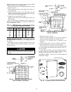
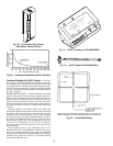
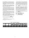
FIELD-SUPPLIED OR HIGH-VELOCITY PRESSURE
TRANSDUCERS — The default pressure transducer in-
stalled at the factory (P/N HK05ZG004) has a range of 0.00
to 0.05 in. wg, which matches an air velocity range of ap-
proximately 225 to 680 fpm. The maximum velocity for op-
timum OAC operation and response, however, is 620 fpm.
If the average duct air velocity is greater than 620 fpm, use
one of the alternate transducers shown in Table 7.
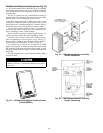
For a field-supplied pressure transducer, use the service
function ( ) to configure the OAC control with
the transducer’s specifications:
OALV = Transducer minimum output voltage
OAHV = Transducer maximum output voltage
OALR = Transducer low pressure
(range minimum output) value
OAHR = Transducer high pressure
(range maximum output) value
Table 7 — OAC Pressure Transducers
CARRIER
PART NO.
MODUS PART
NO.
RANGE
(in. wg)
INDICATED VELOCITY
PRESSURE AT
TRANSDUCER (in. wg)
TRUE VELOCITY PRESSURE
IN DUCT (in. wg)
VELOCITY IN DUCT
(fpm)
Optimum
Range
Theoretical
Range
Optimum
Range
Theoretical
Range
Optimum
Range
Theoretical
Range
HK05ZG004 T40-005C-04-013 0.00 — 0.05 0.013 — 0.037 0.005 — 0.045 0.008 — 0.024 0.003 — 0.029 360 — 620 225 — 680
HK05ZG005 T40-001C-04-012 0.00 — 0.10 0.025 — 0.075 0.010 — 0.090 0.016 — 0.048 0.006 — 0.057 505 — 875 320 — 960
HK05ZG006 T40-003C-04-015 0.00 — 0.30 0.075 — 0.225 0.030 — 0.270 0.048 — 0.144 0.019 — 0.173 875 — 1520 555 — 1665
51