


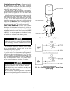
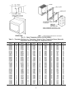
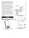

Space Temperature Sensor (Fig. 18) — The space
temperature sensor (SPT) is packaged and shipped inside the
fan section. It is installed on a building interior wall to mea-
sure room air temperature.
The wall plate accommodates both the NEMA (National
Electrical Manufacturers’ Association) standard and the
European
1
⁄
4
DIN (Deutsche Industrie Norm) standard. The
use of a junction box to accommodate the wiring is recom-
mended for installation. The sensor can be mounted directly
on the wall, if acceptable by local codes.
DO NOT mount the sensor in drafty areas such as near
heating or air conditioning ducts, open windows, fans,
or over heat sources such as baseboard heaters or radiators.
Sensors mounted in these areas produce inaccurate readings.
Avoid corner locations. Allow at least 3 ft between the
sensor and any corner. Airflow near corners tends to be re-
duced, resulting in erratic sensor readings.
The sensor should be mounted approximately 5 ft up from
the floor, in the area representing the average temperature.
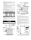
Install the sensor as follows:
1. Remove sensor cover. Using a small blade screwdriver,
insert blade into sensor cover latch slot on bottom of slat.
Gently push upward on the screwdriver to release the cover
latch. Rotate the cover forward as the screwdriver is re-
moved.
2. Snap off the wall plate from the base assembly.
3. Feed the wires from the electrical box through the sensor
base assembly.
4. Using two 6-32 x
5
⁄
8
-in. flat screws, mount the sensor base
assembly to the electrical box.
5. Dress the wires down and inside the perimeter of the sen-
sor base.
6. Attach the wall plate by snapping it onto the sensor base
assembly.
7. Replace the cover by inserting the top inside edge of the
cover over the tab on top of the sensor base assembly and
rotating the cover down. Snap cover on.
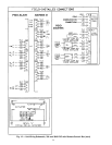
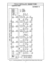
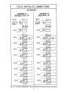
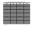
Refer to Field Wiring Connections section, page 52 for
wiring instructions and details. See Table 3 for Thermistor
Resistance vs. Temperature Values.
NOTE: Clean sensor with damp cloth only. Do not use
solvents.
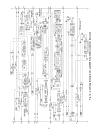
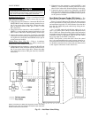
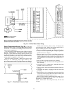
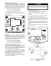
NOTE: Connections for 39NX with integral PIC shown. See wiring
diagrams in Fig. 9 and 12 for terminal connections in 39L control box
and all remote-mount control boxes.
Fig. 16 — Chilled Water Valve Wiring
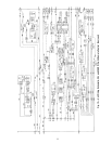
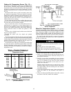
FACTORY WIRING
FIELD WIRING
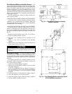
Fig. 17 — Duct Static Pressure Probe
40