


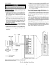
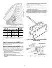
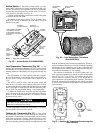
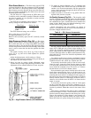

Heat Interlock Relay (Fig. 27) — The heat interlock
relay (HIR) is factory wired and installed on VAV units only.
It is a single-pole, double-throw (SPDT) relay that provides
normally-open and normally-closed contacts to interface with
air terminal units. It allows the air terminals to open when
the PIC unit goes into the heating mode. The contacts are
silver cadmium oxide and are rated as follows:
48 va at 24 vac and .25 power factor
125 va at 115 vac and .25 power factor
125 va at 230 vac and .25 power factor
The contact terminations are no. 6 screw terminals.
NOTE: The HIR is not used in digital air volume control
(DAV) applications.
Fan Relay — The fan relay is factory wired and installed
on all 39L and 39NX units. It is a SPST relay that provides
a normally-open contact. The relay interfaces with the mo-
tor starter circuit and automatically starts/stops the fan when
the HOA switch is in the AUTO mode. The contacts are sil-
ver cadmium oxide and are rated as follows:
48 va at 24 vac and .25 power factor
125 va at 115 vac and .25 power factor
125 va at 230 vac and .25 power factor
The contact terminations are factory wired to TB1.
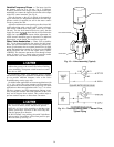
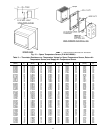
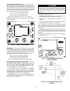
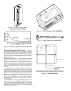
Duct High Humidity Switch (Fig. 28) — The duct
high humidity switch (DHH) is shipped inside the fan sec-
tion. It is used as a safety input when the humidity control
options have been ordered. The DHH adjustment knob pro-
vides settings from 15 to 95% humidity.
Locate the DHH control element in the duct, downstream
of the humidifier. Adjust the DHH to the ASHRAE
(American Society of Heating, Refrigeration, and Air Con-
ditioning Engineers) recommended maximum setting of 80%.
Settings higher than 80% are not recommended.
The DHH is normally mounted in a horizontal position on
the outside surface of the duct with the sensing element ex-
posed to freely circulating air.
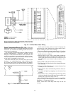
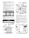
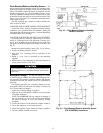
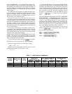
DO NOT install the duct high humidity switch in lo-
cations where excessive moisture, corrosive fumes, and/or
vibration are present. Be sure to allow minimum dimen-
sions from the elbows or junctions as indicated in
Fig. 29.
Mount the DHH as follows:
1. Position the mounting template on the duct. Remove ad-
hesive backing and press template onto duct.
2. Drill four
1
⁄
8
-in. mounting holes as indicated on the
template.
3. Cut out center portion of duct as outlined on template.
4. Mount DHH to duct using screws provided.
For distances up to 500 ft, use 2-conductor 20 AWG
cable to connect the switch to the PIC control box terminals.
Refer to Field Wiring Connections section, page 52 for fur-
ther details.
The DHH adjustment knob provides settings from 15
to 95% relative humidity, The scale range is marked on the
face of the switch. The high humidity set point should be at
least 65%.
NOTE: The duct high humidity switch has a relative humid-
ity differential of 5%.
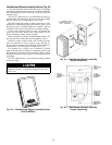
NC
SDA 20 20
COM
NO
1
COIL
2
Fig. 27 — Relay (P/N HK35AB001)
Fig. 28 — Duct High Humidity Switch
(P/N HL38ZG024)
Fig. 29 — Duct High Humidity Switch
Locations
45