


Duct-Mounted Relative Humidity Sensor — The
duct-mounted relative humidity sensor and mounting tem-
plate are packaged and shipped inside the fan section. The
sensor is installed in either the return air ductwork or in the
outside air ductwork. If 2 relative humidity sensors are or-
dered for differential enthalpy control, then the sensors must
be installed in both the return air and outside air ducts. If the
sensor is used for control of a humidifier, install the sensor
in the return air duct.
The PIC controller has a return air relative humidity de-
fault set point of 40%.
LOCATION FOR OUTSIDE AIR RELATIVE HUMIDITY
— Locate the sensor where it accurately measures outdoor
conditions, yet is protected from the elements. During the
unoccupied (fan off) period, the sensor’s location should have
a minimal effect on its readings.
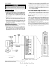
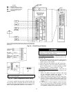
LOCATION FOR RETURN AIR RELATIVE HUMIDITY
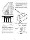
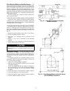
— Locate the sensor at least 6 in. upstream or 15 in. down-
stream of a 90 degree turn in the ductwork. The best loca-
tion is 15 in. downstream of the 90 degree turn of the duct.
The probe should be mounted in the center of the duct. See
Fig. 33.
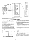
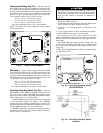
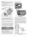
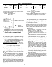
Mount the relative humidity sensor (Fig. 34) as follows.
1. Position mounting template on duct.
2. Drill four
1
⁄
8
-in. mounting holes as indicated on the
template.
3. Punch a 1
1
⁄
8
-in. hole as indicated on the mounting
template.
4. Mount sensor to duct using four no. 8 screws. Install 9-in.
sensor probe into the 1
1
⁄
8
-in. hole.
Never attempt to clean or touch the sensing element with
chemical solvents, as permanent damage to the sensor
will occur.
Mixing Box Linkage— On units with mixing box (MXB)
or filter mixing box (FMB), the actuator and linkage are fac-
tory installed. The actuator is directly linked to the outdoor-
air damper and holds the damper closed. No adjustment is
necessary.
For shipping purposes, the secondary linkage rod con-
necting the outdoor-air and return-air dampers is factory set
for a closed return-air damper.
Adjust the secondary linkage as follows:
1. Open the door of the MXB or FMB to access the return
air damper crankarm.
NOTE: On MXB/FMB with top outdoor-air damper, it
may be necessary to remove the vertical panel holding
the return-air damper to access the return-air damper
crankarm.
2. Loosen the setscrew on the return-air damper crankarm.
3. Move the damper to its full open position.
4. Secure the setscrew on the return-air damper crankarm.
5. Close the MXB or FMB access door.
Fig. 33 — Duct-Mounted Relative Humidity
Sensor Locations
Fig. 34 — Duct-Mounted Relative Humidity Sensor
(P/N HL39ZZ002) Installation
47