


To verify or adjust submaster default values, perform the
following for each controlled device (control loop):
1. Verify that controlled devices (cooling coil valve [CCV],
heating coil valve [HCV]) are properly piped and wired.
2. Using the local interface device, force each controlled
device fully open and fully closed. Make sure the ac-
tuators move smoothly. Sticky or sloppy actuators result
in poor control. They must be corrected, otherwise it may
be impossible to obtain stable control.
3. Verify that all appropriate energy sources are available:
hot water, chilled water, steam, etc.
4. Verify that the system is in the Occupied mode and the
supply fan is running.
5. Verify that the supply fan status indicates ON. If the fan
status if OFF, the control algorithms hold the controlled
devices at the failsafe position.
6. Verify that all forces have been removed.
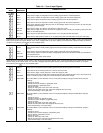
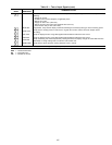
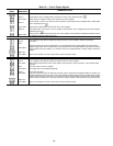
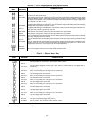
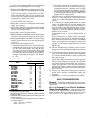
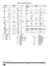
7. Table 24 indicates recommended starting values for SMG,
MPG, and MIG for constant volume and variable air vol-
ume units. Verify that these values have been entered.
8. Verify/adjust the SMG. If the SMG is too large, the loop
tends to oscillate (hunt). If it is too small, the loop reacts
too slowly.
Verify or adjust the SMG as follows:
a. Using the local interface device, force the submaster
reference of the control loop to a value above or be-
low the actual sensor reading. Verify that the actua-
tor responds correctly. If the actuator drives in the
wrong direction, go to the submaster gain (SMG) for
the control loop and reverse the sign of the gain. For
example: If the submaster loop gain is 5.0, change it
to −5.0.
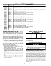
Table 24 — Recommended Gain Starting Valves
GAIN
VALUE
CV VAV
HCV MPG 8.0 0.3*
HCV MIG 0.3 1.5*
HCV SMG† −7.5 −7.5
CCV MPG 8.0 0.3*
CCV MIG 0.3 1.0*
CCV SMG** −7.5 −7.5
MIXD MPG 8.0 0.5*
MIXD MIG 0.3 1.5*
MIXD SMG −7.5 −7.5
IGV MPG — 0.5
IGV SMG — 5.0
EH MPG 8.0 8.0
EH SMG 5.0 5.0
PREHEAT/AO MPG 1.0 0.3
PREHEAT/AO MIG 0.8 0.8
PREHEAT/AO SMG† −3.0 −3.0
PREHEAT/AO SCV†† 100% 100%*
RFVC MPG — 0.5
RFVC SMG — 10.0
HUM MPG 2.0 2.0
HUM SMG 7.5 7.5
*Differs from default value; change the default value to obtain the
recommended starting value shown.
†Values shown are for normally-open valves. If normally-closed valves
are used, see Step 8.
**Values shown are for normally-closed valves. If normally-open valves
are used, see Step 8.
††Values shown are for normally-open valves. If normally-closed valves
are used, subtract initial value specified from 100% to obtain the
correct value. Example:
100% − (SCV N.O.) = (SCV N.C.)
100% − 100% = 0%
b. Observe the operation of the controlled device for a
few minutes. If the device oscillates every few sec-
onds around the forced value, then lower the SMG
by small amounts until the output steadies. If the out-
put to the device responds to a change in temperature
in small increments, then increase the SMG in small
amounts until the output steadies.
NOTE: Do not be alarmed if the submaster sensor sta-
bilizes at a value greater than or less than the forced
value. This is termed the submaster droop offset and is
normal.
9. It is not necessary to adjust the submaster loop center
value, as the master loop will adjust the submaster ref-
erence as required to satisfy its set point. However, it
may be desirable to keep the submaster droop to a mini-
mum. This is most often required for heating coil loops,
(especially on steam coils where the control valve has a
tendency to be oversized).
If the submaster droop is too large, adjust the SCV as
follows:
If the submaster droop is positive (actual value greater
than reference value), the SCV should be decreased for
HCV and IGV loops and increased for CCV and MIXD
loops. If the submaster droop is negative (actual value
less than reference value), the SCV should be increased
for HCV and IGV loops and decreased for CCV and
MIXD loops.
10. Once the submaster loop is adjusted, remove all forces
and proceed with verification and adjustment of master
loop.
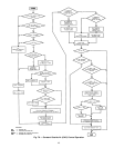
11. To check the master loop, create an error in the master
loop. For example: Change the actual space temperature
to a value less than the heating set point or greater than
the cooling set point.
Observe system (loop) response for 10 to 20 minutes to
verify stable control. After 10 minutes if the output con-
tinues to swing full open to full closed, lower the MPG
and observe again. Do this until the loop operation is
stable. After 10 minutes, if the loop does not seem to
respond (little change in submaster reference), increase
the MPG and observe again. Do this until stable opera-
tion is achieved.
12. Once you are satisfied with loop operation, remove all
forces which may have been initiated during this
procedure.
13. Repeat steps 1-12 until all loops have been checked.
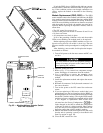
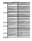
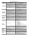
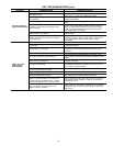
VALVE TROUBLESHOOTING
General —
To facilitate troubleshooting the valve, it may
be necessary to disassemble the electronic actuator from the
valve body.
All
1
⁄
2
-in. Through 1
1
⁄
4
-in. Electric Hot Water/
Steam Valve Assemblies —
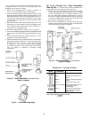
A high-temperature link-
age extension is supplied to help insulate the hydraulic ac-
tuator from heat. See Fig. 80. Mount valves so that valve
stem is at a 35° to 45° angle from vertical. See Fig. 81.
109