


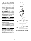
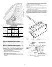
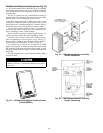
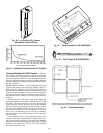
Wall-Mounted Relative Humidity Sensor (Fig. 30)
—
The wall-mounted relative humidity sensor is packaged
and shipped inside the fan section. It is installed on interior
walls to measure the relative humidity of the air within the
occupied space.
The use of a junction box to accommodate the wiring is
recommended for installation. The sensor may be mounted
directly on the wall, if acceptable by local codes.
DO NOT mount the sensor in drafty areas such as near
heating or air conditioning ducts, open windows, fans, or over
heat sources such as baseboard heaters or radiators. Sensors
mounted in those areas will produce inaccurate readings.
Avoid corner locations. Allow at least 3 ft between the
sensor and any corner. Airflow near corners tends to be re-
duced, resulting in erratic sensor readings.
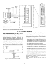
Sensor should be vertically mounted approximately 5 ft
up from the floor, beside the space temperature sensor.
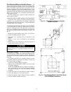
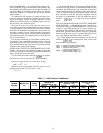
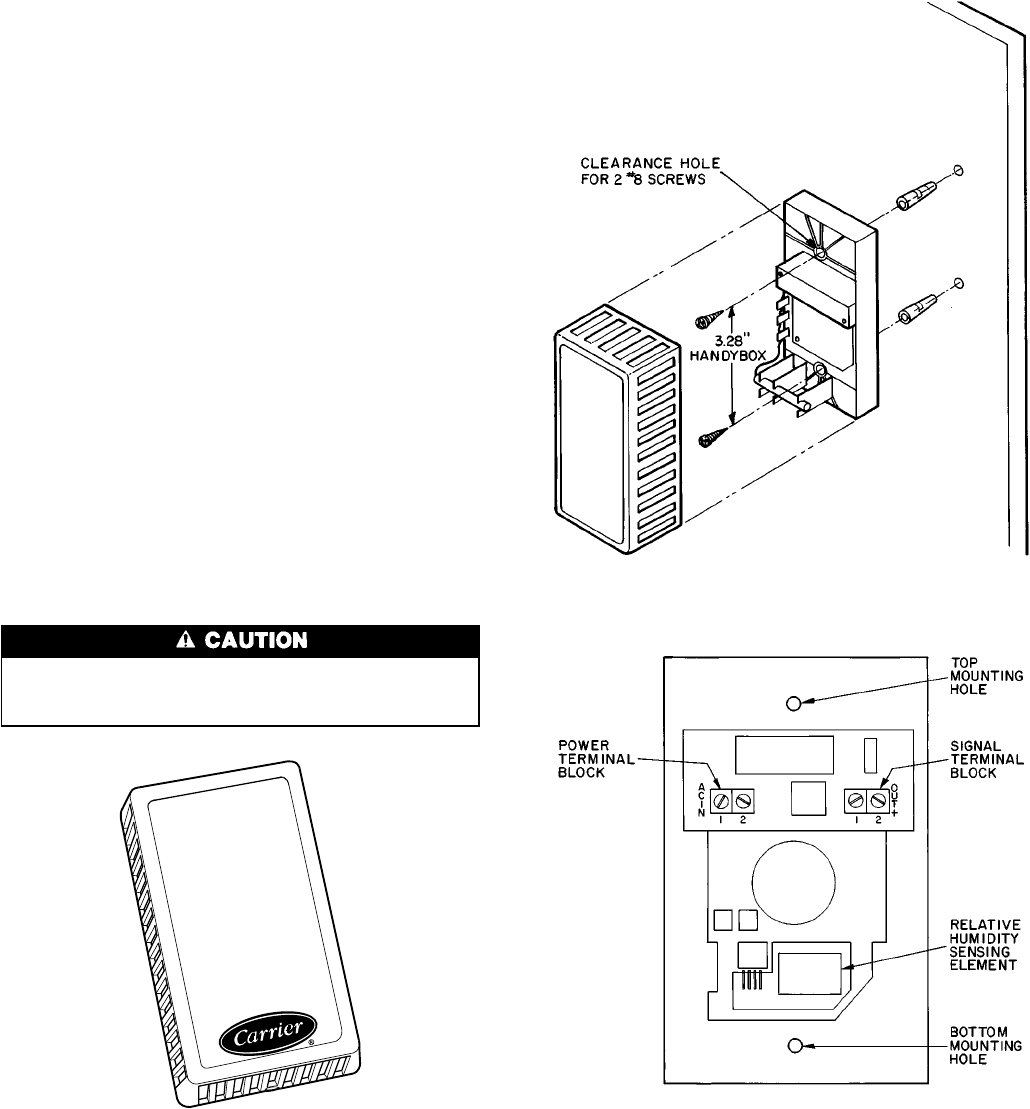
Install the sensor using 2 screws and 2 hollow wall an-
chors (if required); do not overtighten screws. See Fig. 31.
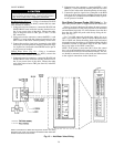
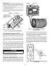
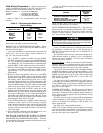
Sensor must be mounted with terminals ACIN and OUTϩ
located at the top of the sensor as shown in Fig. 32.
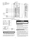
For distances up to 500 ft, use 4-conductor 20 AWG
cable (2 twisted pairs, no shield) to connect the sensor to the
PIC control box terminals and power supply. Refer to Field
Wiring Connections section, page 52 for wiring instructions
and details.
The PIC controller has a space relative humidity default
set point of 40%.
Never attempt to clean or touch the sensing element with
chemical solvents, as permanent damage to the sensor
will occur.
Fig. 30 — Wall-Mounted Relative Humidity Sensor
(P/N HL39ZZ001)
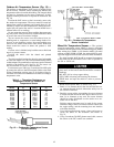
Fig. 31 — Wall-Mounted Relative Humidity
Sensor Installation
Fig. 32 — Wall-Mounted Relative Humidity
Sensor Positioning
46