


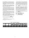

Table 9 — Recommended Actuators
PART
NO.
VOLTAGE
(50/60 Hz)
VA (24 vac)
IMPEDANCE
(Ohms)
SIGNAL INPUT
(mA)
DAMPER AREA
(sq ft)
TORQUE
(in.-lb)
STROKE
Parallel Opposed
HF27BB006 24 18 82.5 4 to 20 8.4 10.8 15 2 in.
HY27BB001* 24 60 250.0 4 to 20 42 54 50 180°
HF27BB010 24 44 82.5 4 to 20 106 137 190 3
1
⁄
2
in.
*Shipped with drive HF39CB001, which must be field-installed on actuator.
NOTES:
1. All actuators are spring return.
2. Damper area ratings are nominalandare based on standard (NOTlow leak)
dampers at 1.0 in. wg pressure and 2000 fpm velocity.
3. Actuator wire coding is as follows:
HF27BB006 - BLACK and WHITE (24 vac)
RED (ϩ signal)
GREEN (− signal)
HY27BB001 - BLACK and WHITE (24 vac)
ORANGE (ϩ signal)
BLUE (− signal)
HF27BB010 - WHITE/BLUE and BLACK (24 vac)
RED (ϩ signal)
GREEN (− signal)
4. Actuator HH27BB006 is equipped with 20 ft of plenum cable. Wires for ac-
tuators HY27BB001 and HF27BB010 are in the actuator junction box.
5. Actuators are available as an option when ordered with the unit.
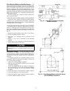
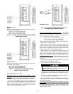
4a. For the return-air damper (RAD) actuator, connect the
positive (ϩ) lead to TB2, terminal 6. Connect the nega-
tive (−) lead to TB2, terminal 7.
b. If the actuator is factory-supplied, connect the actua-
tor’s 24 vac power wires to TB2, terminals 21 and 22.
If the actuator is field supplied, connect the power wires
to a separate, isolated 24 vac power source.
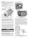
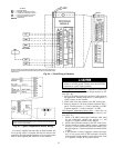
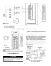
Field-Supplied Two-Position Damper — The factory-
supplied SPDT relay must be field-installed and wired. The
relay contacts are rated as follows:
48 va at 24 vac and .25 service factor
125 va at 115 vac and .25 service factor
125 va at 230 vac and .25 service factor
The relay provides a set of contacts (normally open and nor-
mally closed) using no. 6 screw terminals; the 24 vdc coil
connections are through
1
⁄
4
-in. quick connects.
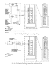
Using a 20 AWG twisted cable, connect the relay coil con-
tacts 1 and 2 to the processor module pins 41 and 42. See
Fig. 48.
To connect the field-supplied two-position damper actua-
tor (Fig. 48): Connect one contact of the actuator to the
normally-open contact of the relay. Connect the common con-
tact of the relay to one leg of the power source. Connect the
other contact of the actuator to the other leg of the power
source.
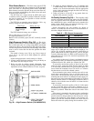
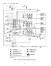
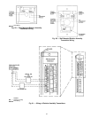
SMOKE CONTROL OPTION — The smoke control option
includes 3 relays which control the 4 different modes of the
option. These relays are factory wired. Terminal block 5 (TB5)
provides an easy means to wire the field-supplied smoke con-
trol panel to the PIC controller on the 39L or 39NX unit. See
Fig. 49 and 50.
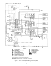
The approved building fire alarm system must provide 4
different normally-open dry contact closures. A field-
supplied 24 vac, double-pole, double-throw (DPDT) fire shut-
down (FSD) relay rated for the application (240 vac with a
10 amp minimum) is required.
All power going through the smoke control panel dry con-
tacts and the FSD relay coil is furnished by the PIC control
box. A 24 vac fused power source uses a factory-installed
3 amp in-line fuse. See Fig. 49 or 50 for smoke control op-
tion wiring details.
Wire as follows:
1. Disconnect all power at the unit, PIC control box,
return fan (if applicable), and fire panel.
2. Wire the supply fan motor starter per Fig. 8.
3. If applicable, wire the return fan as shown in Fig. 49 or
50.
NOTE: Return fan power may be different from supply
fan power.
4. Connect leads from the return fan HOA switch to
terminals 9 and 10 of TB5.
5. Wire the first set of contacts of the DPDT FSD. For fire
shutdown of the unit from a local smoke detector, wire
ONLYthe normally-closed contacts (NEC, class 1 power
rated) to the hot leg of the fan power supply and ter-
minal 2 of TB1.
6. Terminal 8 of TB5 is internally connected to ground.
Connect one side of the EVAC, PURG, and PRES dry
contacts of the smoke control panel to terminal 8 of TB5.
7. Connect the other side of the PRES dry contact to ter-
minal 3 of TB5. Connect the other side of the PURG
dry contact to terminal 4 of TB5. Connect the other side
of the EVAC dry contact to terminal 5 of TB5.
8. Connect the normally-open dry contacts of the FSD de-
vice (smoke detector with auxilary relay and/or smoke
control panel dry contact set) to terminal 1 and 2 of TB5.
9. Connect the 24 vac relay coil of the FSD relay to ter-
minals 1 and 8 of TB5.
10. Connect the second pole of the FSD relay to the hot leg
of the return fan power supply and to terminal 11 of TB5.
Refer to Fig. 49 or 50 for point-to-point wiring of the smoke
control option inside the PIC control box.
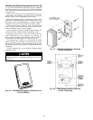
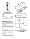
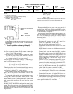
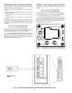
Fig. 46 — Exhaust Damper Actuator Wiring (Smoke
Control Option or Modulating Dampers)
LEGEND
Field Wiring
EXD — Exhaust Air
Damper Actuator
54