


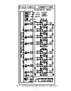
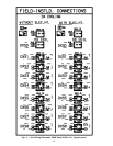
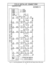
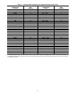
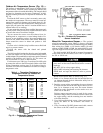

Table 2 — Junction Box Connections for Optional Remote Control Box
REMOTE
CONTROL BOX
LOCATION
CONTROL
BOX
TERMINAL
FAN SECTION
JUNCTION BOX
SIGNAL
JUNCTION
BOX
TERMINAL
MPSIO 2 SAT — BLK 1
MPSIO 3 SAT — RED 2
MPSIO 8 MAT — BLK 3
MPSIO 9 MAT — RED 4
TB3 10 FLTS — BLK 5
MPSIO 28 FLTS — RED 6
TB3 10 LTT — K3 7
MPSIO 13 LTT — K1 8
TB2 19 OAD — BLK 9
TB2 20 OAD — WHT 10
TB2 6 OAD — GRN 11
MPSIO 40 OAD — RED 12
TB2 21 RAD — BLK 13
TB2 22 RAD — WHT 14
TB2 7 RAD — GRN 15
TB2 6 RAD — RED 16
TB2 27 EXD — BLK 17
TB2 28 EXD — WHT 18
TB2 8 EXD — GRN 19
TB2 7 EXD — RED 20
TB2 15 SFAN1 — BLK 21
TB2 16 SFAN1 — WHT 22
MPSIO 38 SFAN1 — GRN 23
MPSIO 37 SFAN1 — RED 24
TB2 17 SFAN2 — BLK 25
TB2 18 SFAN2 — WHT 26
TB2 23 RFAN1 — BLK 27
TB2 24 RFAN1 — WHT 28
SPSIO 38 RFAN1 — GRN 29
SPSIO 37 RFAN1 — RED 30
TB2 25 RFAN2 — BLK 31
TB2 26 RFAN2 — WHT 32
SPSIO 12 PH — BLK 33
SPSIO 11 PH — RED 34
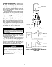
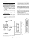
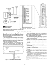
NOTES:
1. Pneumatic tubing to connect the airflow sensor in the fan to the remote control box is bundled with the internal PIC wiring to the junction box,
but does not enter the box. Route tube directly to remote control box along with conduit containing wiring from junction box to remote control box.
2. See Legend on page 7.
37