


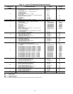
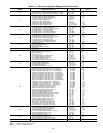

— Used to read or change field configuration
of fan tracking. See Example 13.
------------------------------------------------
— Used to read or change factory configura-
tion of humidity control.
------------------------------------------------
— Used to read or change factory configura-
tion of alarm limits. See Example 14.
------------------------------------------------
— Used to read or change field configuration
of analog temperature control. See Example 15.
------------------------------------------------
— Used to read or change field configuration
of discrete temperature control. See Example 16.
------------------------------------------------
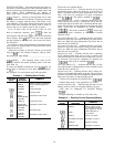
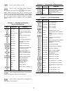
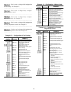
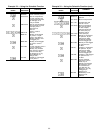
Example 13 — Configuration of Fan Tracking
KEYBOARD
ENTRY
DISPLAY
RESPONSE
COMMENTS
FANTRACK Fan tracking field configuration
subfunction of service function
SVUL 1.5
Supply velocity upper limit
= 1.5 in. wg
SVUL 2.0
Supply velocity upper limit
changed to 2.0 in. wg
RVUL 1.5
Scroll past return velocity upper
limit (1.5 in. wg)
SDAR 0 Supply duct area = 0
SDAR 8 Supply duct area changed to
8 sq ft. (Enter whole numbers;
decimals not accepted)
RDAR 6
Scroll past return duct area
(6 sq ft)
MPG 0.5
Scroll past master proportional
gain
MIG 0.5
Scroll past master integral
gain
MDG 0.0 Master derivative gain
MDG 4
Master derivative gain
changed to 4
SMG 10 Scroll past submaster gain
SCV 50
Scroll past submaster
gain center value
SMR N Submaster reference value
(calculated and updated by the
software)
SMR X
Submaster reference value
forced to X value
SMR N
Submaster reference value
force is removed
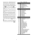
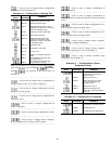
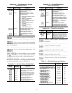
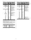
Example 14 — Configuration of Alarm Limits
KEYBOARD
ENTRY
DISPLAY
RESPONSE
COMMENTS
ALRMLIMT
Alarm limit field configuration of
subfunction of service function
SPLO 65
Scroll past space temperature low
limit (occupied mode)
SPHO 80
Scroll past space temperature high
limit (occupied mode)
SPLU 45
Scroll past space air temperature
low limit (unoccupied mode)
SPHU 100
Scroll past space air temperature
high limit (unoccupied mode)
SALO 45
Supply-air temperature low limit set
at 45 F (occupied mode)
SALO N Supply-air temperature low limit
changed to N, whereN=new
value within allowable range
(−10 F to 245 F)
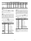
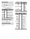
Example 15 — Configuration of Analog
Temperature Control
KEYBOARD
ENTRY
DISPLAY
RESPONSE
COMMENTS
AO CTRL Analog temperature control
configuration subfunction of
service function
MPG 5.0
Scroll past master proportional
gain
MIG 0.3 Scroll past master integral gain
MDG 0.0 Scroll past master derivative gain
SMG −5.0 Scroll past submaster gain
SCV 50
Scroll past submaster center
value
FOV 40 Scroll past fan OFF value
SEN 0
Controlling temperature sensor
(none configured)
SEN 1 Controlling temperature sensor
configured to sensor 1. Sensor
codes as follows:
1 - Supply-air temperature sensor
(standard)
2 - Outdoor-air temperature
sensor (standard)
3 - Mixed-air temperature sensor
(optional)
6 - Space temperature sensor
(standard)
7 - Return-air temperature sensor
(standard)
34 - Other optional sensor
SMR X Submaster reference value
SMR N
Submaster reference value
forced to N value
SMR X Force removed from submaster
reference value. Display shows
last value prior to force
86