


START-UP
Initial Check
IMPORTANT: Do not attempt to start unit, even mo-
mentarily, until the following steps have been com-
pleted.
1. Verify unit has been installed per the Installation, Start-
Up, and Service Instructions shipped inside the unit.
2. Verify that all auxiliary components (valves, sensors, etc.)
have been installed and wired to the PIC control box.
3. Verify that the motor starter and HOA switch have been
installed and wired.
NOTE: HOA switch must be in OFF position.
4. Check to be sure area around unit is clear of construc-
tion dirt and debris.
5. On VAV units, verify that the static pressure probe and
associated piping have been installed.
6. Verify that:
Chilled water valve is in its normal position.
Hot water/steam valve is in its normal position.
Outside-air damper is closed.
Return-air damper is open.
Inlet guide vanes are closed (VAV units).
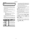
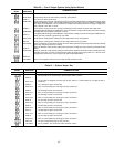
7. Set control configurations. Units are shipped with ap-
plicable controls programmed to the default values shown
in Table 16.
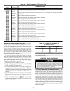
8. Set unit set points. Units are shipped with the set point
default values shown in Table 17. If a different set point
is required, change as shown in the following example:
KEYBOARD
ENTRY
DISPLAY
RESPONSE
COMMENTS
SETPOINT System set points
OHSP 68.0 Present occupied heat set point
is 68.0
OHSP 59.0 Key in 59 and press ENTR, display
shows new occupied heat set point
is 59
OCSP 78.0 Present occupied cooling set point
is 78.0
OCSP 70.0 Key in 70 and press ENTR, display
shows new occupied cooling set
point is 70
Unit is shipped with the NTFC, Demand Limit, Tem-
perature Reset, Optimal Start, Occupied Heating, and
Fan Tracking functions disabled. If these functions are
desired, refer to Control Operation, Programming Func-
tions section beginning on page 81.
9. Check tightness of all electrical connections.
10. Turn on control power by turning the ON/OFF switch
located in the PIC control box to ON.
11. Perform Quick Test to make sure controls are operating
properly. See the following section.
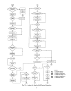
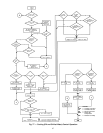
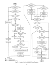
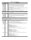
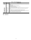
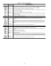
Quick Test — The Quick Test feature allows the service
technician to individually test all inputs and outputs of the
control system. See Tables 18-22.
The test function operates the Quick Test diagnostic pro-
gram. The test subfunctions energize the valves, dampers,
and inlet guide vanes (VAV units).
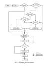
To start Quick Test, set HOA switch to OFF. Verify sup-
ply fan stops. Quick Test does not operate if supply fan sta-
tus is ON.
A test can be terminated by pressing . Pressing af-
ter a test has started advances the system to the next test.
Once the next test is displayed you can start the test by
pressing , advance past it by pressing , or back up
by pressing . The unit remains in Quick Test until
and then are pressed. At that time the unit
reverts to automatic control.
If the keyboard is not used for 10 minutes, the display
automatically returns to the rotating default display. You
must press and to exit Quick Test and then
press to restart the procedure.
103