


CONTROL OPERATING SEQUENCE
Constant Volume and Variable Air Volume Units
TWO-POSITION DAMPER CONTROL — Two-position
damper control opens or closes field-supplied and installed
two-position outdoor-air dampers in order to provide mini-
mum outdoor air ventilation.
If the supply fan is OFF, the damper is closed. If the sup-
ply fan is ON, the control determines if the unit is in the
OCCUPIED mode. If unit is in the OCCUPIED mode, the
dampers open. If unit is in the UNOCCUPIED mode, the
dampers close.
FILTER STATUS CONTROL — This control sequence moni-
tors one or more airflow switches which measure the dif-
ferential pressure between the upstream and downstream side
of a filter.
When the filter becomes dirty or needs to be replaced, the
airflow switches send a discrete signal to the processor mod-
ule. This, in turn, generates an alarm at the Local Interface
Device or Building Supervisor.
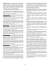
FAN CONTROL — The supply fan is started or stopped based
on the occupancy schedule, adaptive optimal start, night-
time free cooling, unoccupied heating, unoccupied cooling,
demand limiting, night purge, or timed override.
The start of an occupied period is determined by either
the occupancy schedule or optimal start. If optimal start is
not selected, the supply fan starts at the occupied time en-
tered in the occupancy schedule. If optimal start is selected,
the fan starts at the calculated start time. The fan stops at the
unoccupied time entered in the occupancy schedule. (Timed
override may be used to extend the occupied period between
1 and 4 hours.)
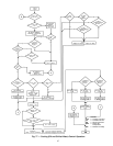
During the unoccupied period, whenever the space tem-
perature falls below the unoccupied heating set point or rises
above the unoccupied cooling set point, the supply fan en-
ergizes and runs until the space temperature returns to within
the required limits.
The supply fan can also run between the hours of
3:00 am and 7:00 am when the unit is in the Nighttime Free
Cooling mode to pre-cool the space prior to the Occupied
period.
Constant volume units that are subject to demand limiting
stop the supply fan whenever a loadshed command is re-
ceived from the CCN Loadshed option. The supply fan re-
mains OFF until the loadshed command is cleared or the in-
ternal maximum loadshed timer expires.
NIGHTTIME FREE COOL (NTFC) — Nighttime free cool-
ing is used to start the supply fan to precool the building’s
interior using outside air. This delays the need for mechani-
cal cooling when the system enters the Occupied mode.
The system determines if the outside conditions (tempera-
ture and enthalpy) are suitable for outside cooling. If so, the
supply fan is energized and the dampers modulate open. Once
the space has been sufficiently cooled, the fan stops.
If the outside air conditions are not suitable, the fan
remains OFF.
The unit must have mixed-air dampers to operate NTFC.
NTFC is scheduled to run only between the hours of
3:00 am and 7:00 am.
NIGHT PURGE — During the unoccupied period, this fea-
ture starts the fans and opens the mixed-air dampers to re-
move stagnant air and airborne pollutants from the building
space.
If the current time is within the configured night purge
duration, the control reads the outdoor air temperature and
determines the mixed-air damper position. If the outdoor air
temperature is less than the configured NTFC lockout tem-
perature, the system sets the mixed-air dampers at the con-
figured low temperature position. If the outdoor-air temperature
is greater than the NTFC set point, or the enthalpy is high,
the system sets the dampers at the configured high tempera-
ture position.
When the outside-air temperature is below the NTFC set
point and the low temperature night purge damper position
is set to zero, night purge is not performed. Also, when the
outside air temperature is above the NTFC set point and en-
thalpy is high, if the high temperature night purge damper
position is set to zero, night purge is not performed.
Night purge ends when the occupied time period begins.
QUICK TEST — The Quick Test is initiated and controlled
at the local interface device (HSIO). It allows the service
person or building owner to test all inputs and outputs of the
PIC controls. When used, it displays all current values of
input channels and allows the user to exercise all output
channels.
Quick test suspends all process algorithms and forces all
outputs with a service priority.
All service forces are removed when Quick Test is exited
and control is returned to the process algorithms.
ANALOG OUTPUT TEMPERATURE CONTROL/
PREHEAT COIL CONTROL — The analog output tem-
perature control adjusts an analog output to a fixed set point,
based on any analog temperature sensor connected to the unit.
(Applicable sensors are: space temperature sensor, outside-
air temperature sensor, mixed-air temperature sensor, supply-
air temperature sensor, and return-air temperature sensor.)
If the fan is ON, the control identifies the controlling tem-
perature sensor, reads the sensor and compares the tempera-
ture to the configurable set point. It then calculates the tem-
perature required to satisfy the conditions.
The calculated value is compared to the actual tempera-
ture and the corresponding output is modulated to the
required position.
The preheat coil control adjusts the steam or hot water
valve. The valve is modulated to raise the temperature of
incoming outside air. The control uses a sensor downstream
from the preheat coil to monitor the air temperature.
If the supply fan is OFF, the heating valve is modulated
to maintain the desired minimum duct temperature (fan off
value).
If the supply fan is on and the entering-air temperature is
below the set point value, the heating valve is modulated to
obtain the desired leaving-air temperature.
92