


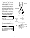
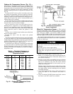
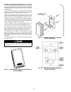

Outdoor-Air Temperature Sensor (Fig. 19) —
The outdoor-air temperature (OAT) sensor is shipped inside
the fan section. The OAT sensor continuously monitors the
temperature of the air outside the building. The integral shield
prevents ice formation on the sensor conductors. A field-
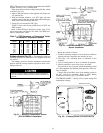
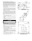
supplied conduit junction box is required for installation. See
Fig. 20.
Position the OAT sensor so that it accurately senses only
the outdoor-air temperature. The sensor must be located up-
stream from outside air dampers and located where it is un-
affected by interior and duct temperatures. During the unoc-
cupied (fan off) period the sensor’s location should have a
minimal effect on its readings.
Do not mount the sensor in direct sunlight. Inaccurate read-
ings may result. It may be necessary to field-fabricate a shield
to protect the sensor from direct sunlight.
Do not mount the sensor near the exhaust from air-
handling units or compressors, or near leakage drafts of in-
door air, or near shrubbery or trees. Inaccurate readings may
result. Do not mount under direct water runoff. Water may
freeze around the sensor in winter and produce a false
reading.
If sensor wire is shielded, strip back the sensor shield and
tape it to prevent contact.
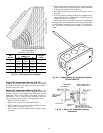
Position the sensor with the slotted end pointed
downward.
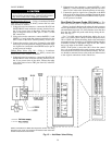
The field-supplied junction box housing must be threaded
to screw onto a male
1
⁄
2
-in. NPT electrical metal tubing (EMT)
conduit adaptor. The assembled box and sensor must be mounted
parallel to the building wall. See Fig. 20. The sensor can
also be installed on a roof or other location.
For distances up to 500 ft, use 2-conductor 20 AWG cable
to connect the sensor to the PIC terminals. Refer to the Field
Wiring Connections section, page 52 for further wiring in-
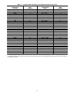
structions. See Table 4 for thermistor resistance according to
temperature value.
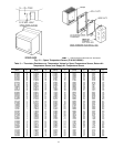
Table 4 — Thermistor Resistance vs
Temperature Values for Outdoor-Air
Temperature Sensor
RESISTANCE
(Ohms)
TEMPERATURE
(F)
RESISTANCE
(Ohms)
TEMPERATURE
(F)
168,250 −40 5,000.0 77
121,350 −31 4,028.5 86
88,500 −22 3,265.0 95
65,200 −13 2,663.3 104
48,535 −4 2,185.0 113
36,476 5 1,801.5 122
27,665 14 1,493.0 131
21,165 23 1,244.0 140
16,325 32 1,041.5 149
12,695 41 876.0 158
9,950 50 739.5 167
6,245 68 627.5 176
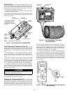
Mixed-Air Temperature Sensor — The optional
mixed-air temperature sensor (MAT) is factory wired and
installed on all units with a factory-installed mixing box (MXB),
filter mixing box (FMB), or air blender (AMX). On units
without an AMX, MXB, or FMB, the optional MAT is pack-
aged and shipped inside the fan section for field installation.
The field-installed MAT should be mounted downstream
of the return air duct and filters, but as close as possible to
the 39L or 39NX unit.
AVOID repeated bending of copper tubing, as this will
place stress on the sensor element and lead to eventual
breakage.
DO NOT fold or crimp copper tubing.
USE CARE in forming and securing the element.
STRIP back and tape the shield in order to prevent
contact.
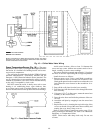
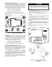
Mount field-installed MAT as follows (Fig. 21):
1. Punch a 1-in. diameter hole in the duct and feed the sen-
sor element through the hole. Mount the utility box on
the outside of the duct.
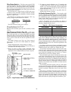
2. Bend the copper tubing surrounding the sensor element
to conform to the area of the duct. Do not bend it to less
than 2
1
⁄
2
in. diameter on any turn. The sensor element
should be evenly distributed over the entire cross sec-
tional area of the duct.
Existing support structures may be used for the sensor
element, as long as there is no metal-to-metal contact with
the copper tubing, and the mounting does not interfere
with other functions.
3. Use a field-supplied plastic spacer, clamp, and screws to
secure the sensor in the airstream. See Detail A,
Fig. 21.
4. Using 2-conductor 20 AWG plenum-rated cable, connect
the sensor to the PIC control box terminals.
Fig. 19 — Outdoor-Air Temperature Sensor
(P/N HH79NZ023)
Fig. 20 — Outdoor-Air Temperature
Sensor Installation
42