


VALVE WIRING
Valves MUST be connected to the correct processor mod-
ule terminal to operate properly. Damage to the actuator
may occur if the valve is improperly connected.
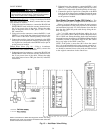
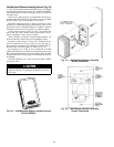
Hot Water Valves (Fig. 15) — Using a 4-conductor 20 AWG
cable (two twisted pairs, no shield), connect the hot water
valve actuator as follows:
1. Using twist-on wire connectors, connect the BLACK and
WHITE/BLUE leads inside the actuator junction box to
the 24 vac power wires of the cable. Connect the other
ends of the power wires to TB2, pins 11 and 12, in the
PIC control box.
2. Using twist-on wire connectors, connect the RED (ϩ) and
GREEN (−) leads inside the actuator junction box to the
other 2 wires in the cable. Note the polarity of each wire.
3. Connect the positive signal wire (connected to the RED
lead) to pin 43 on the processor module. Connect the nega-
tive signal wire (connected to the GREEN lead) to pin 44
on the processor module.
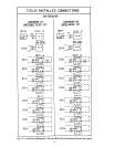
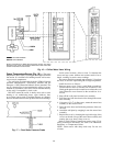
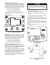
Chilled Water Valves (Fig. 16) — Using a 4-conductor
20 AWG cable (two twisted pairs, no shield), connect the
chilled water valve actuator as follows:
1. Using twist-on wire connectors, connect the BLACK and
WHITE/BLUE leads inside the actuator junction box to
the 24 vac power wires of the cable. Connect the other
ends of the power wires to TB2, pins 9 and 10, in the PIC
control box.
2. Using twist-on wire connectors, connect the RED (ϩ) and
GREEN (−) leads inside the actuator junction box to the
other 2 wires in the cable. Note the polarity of each wire.
3. Connect the positive signal wire (connected to the RED
lead) to pin 46 on the processor module. Connect the nega-
tive signal wire (connected to the GREEN lead) to pin 47
on the processor module.
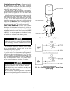
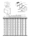
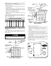
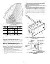
Duct Static Pressure Probe (VAV Units) — The
duct static pressure probe is shipped inside the control box.
Select a location in the ductwork where the static pressure
will be representative of the static pressure to be monitored
and maintained (typically 2/3 of the distance down the duct
from the fan). Install the probe with the tip facing the air-
flow. See Fig. 17.
Use
1
⁄
4
-in. OD approved polyethylene tubing for up to
50 ft (
3
⁄
8
-in. OD for 50 to 100 ft) to connect the probe to the
39L or 39NX unit. Route the tubing back to the mechanical
room and connect the tubing to the bulkhead fitting labelled
H (HIGH), located on the bottom edge of the 39L control
box or top edge of the 39NX control box.
NOTE: If the probe is more than 100 ft from the control
box, it is recommended that the static pressure sensor be re-
moved from the control box and mounted remotely. The sen-
sor should be mounted closer to the probe and then rewired
to the original connections in the control box.
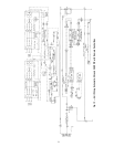
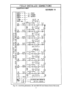
NOTE: Connections for 39NX with integral PIC shown. See wiring
diagrams in Fig. 9 and 12 for terminal connections in 39L control box
and all remote-mount control boxes.
Fig. 15 — Hot Water Valve Wiring
39