


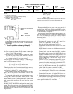
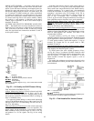

The 24 vac power source(s) to both duct mounted and
wall mounted relative humidity transmitters MUST be
isolated. Connecting either side to a ground will per-
manently damage the sensor.
The power for the relative humidity transmitters may be
sourced from the valve 24 vac power source at wire no. 6
and 7 or at wire no. 4 and 5.
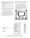
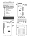
Connect the signal wires as follows: Secure one wire to
the terminal labelled OUT ϩ (located at the right of terminal
block OUT). Secure the other wire to the negative signal
output terminal (terminal adjacent to the terminal labelled
OUT ϩ). Run the twisted pair of signal wires to the PIC
control box. Observe all local code requirements.
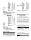
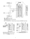
Outdoor Relative Humidity Transmitter: Connect the posi-
tive (ϩ) wire to pin 31 of the processor module. Connect the
negative (−) wire to pin 32 of the processor module.
Return Air or Space Relative Humidity Transmitter;
Connect the positive (ϩ) wire to pin 10 of the processor mod-
ule. Connect the negative (−) wire to pin 11 of the processor
module. See Fig. 61.
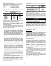
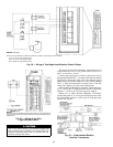
Field Wiring
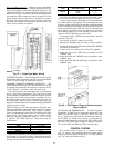
NOTE: The relay furnished is a SPDT relay with silver cadmium oxide contacts, rated as follows:
48 va at 24 vac and .25 power factor
125 va at 115 vac and .25 power factor
125 va at 230 vac and .25 power factor
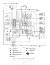
Fig. 56 — Wiring of Two-Stage Humidification Control Relays
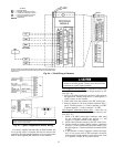
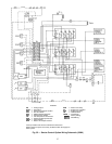
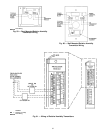
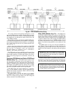
Field Wiring
NOTE: Connections for 39NX with integral PIC shown. See wiring diagrams in
Fig. 9 and 12 for terminal connections in 39L control box and all remote-mount
control boxes.
Fig. 57 — Wiring of the Duct
High Humidity Switch
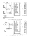
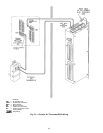
Fig. 58 — Field-Installed Relative
Humidity Transmitters
60