


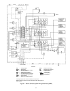
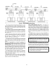

All system software and operating intelligence is in the
processor (PSIO master) module, which controls the unit.
This module monitors and controls conditions through input
and output ports and through the option (PSIO slave) and
relay (DSIO) modules.
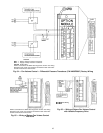
The machine operator communicates with the PSIO mas-
ter through the local interface device (HSIO). Communica-
tions between the PSIO and other modules is accomplished
by a 3-wire sensor bus that runs in parallel between mod-
ules. See Fig. 73.
On the sensor bus terminal strips, terminal 1 of the PSIO
module is connected to terminal 1 of each of the other mod-
ules (see Fig. 73). Terminals 2 and 3 are connected in
the same manner. If a terminal 2 wire is connected to
terminal 1, the system does not work.
The PSIO master and slave and DSIO are all powered from
a 21 vac power source connected to terminals 1 and 2 of the
power input connector on each module. Refer to the 39L or
39NX unit wiring diagram for transformer locations and
wiring.
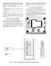
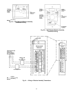
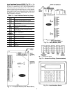
Processor (PSIO Master) and Option (PSIO Slave)
Modules (Fig. 71) —
The PSIO master module moni-
tors and controls components such as the supply fan, cool-
ing and heating coil valves, inlet guide vanes, and mixed-air
dampers. The PSIO slave module provides additional inputs
and outputs to the PSIO master for options such as return
fan volume, humidifier, smoke, and air quality control. The
processor and option modules are factory installed.
Each PSIO input and output channel has 3 terminals;
only 2 of the terminals are used. The unit application de-
termines the terminal connections. Refer to the unit wiring
diagram for terminal numbers.
The PSIO address switches are factory set at address
01 (master) and 31 (slave). Use a local or remote HSIO or
the CCN to change the unit address. Do NOT change the
address switches on the PSIO modules.
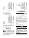
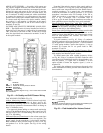
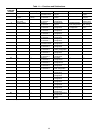
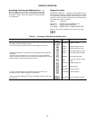
Relay (DSIO) Module (Fig. 72) — The DSIO mod-
ule provides additional inputs and outputs to the PSIO mas-
ter for electric heater and direct expansion coil staging. The
DSIO module is factory installed. If only one DSIO module
is used for electric heat or DX cooling, the DSIO address
switches are factory-set at 19. If 2 DSIO modules are used
for electric heat and DX cooling, the heat module is set to
address 19 and the cooling module is set to address 49. See
Table 1.
The DSIO inputs on strip J3 are discrete (ON/OFF) in-
puts. When 24 vac are applied across the 2 terminals, the
corresponding channel reads one state. When no power is
applied across the terminals, the channel reads the opposite
state.
IMPORTANT: The 24 vac inputs on J3 of the DSIO
module are polarized, with one side tied to earth ground.
The grounded side of the signal must be connected to
the even-number pins.
Terminal strips J4 and J5 are internal relays whose coils
are powered on and off by a signal from the microprocessor.
The relays switch the circuit to which they are connected.
Only Class II power should be applied to these connections.
IMPORTANT: Use only the normally-open contacts
on DSIO modules. These contacts have internal snub-
bers that protect the control modules from destructive
arcing produced by switching inductive loads. NEVER
use the normally-closed contacts.
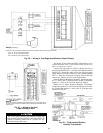
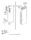
Fig. 69 — CCN Communication Wiring
65