


4-Port Interface Module LEDs
5-5
4-Port Interface
Module LEDs
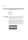
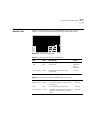
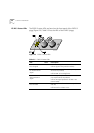
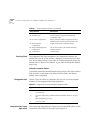
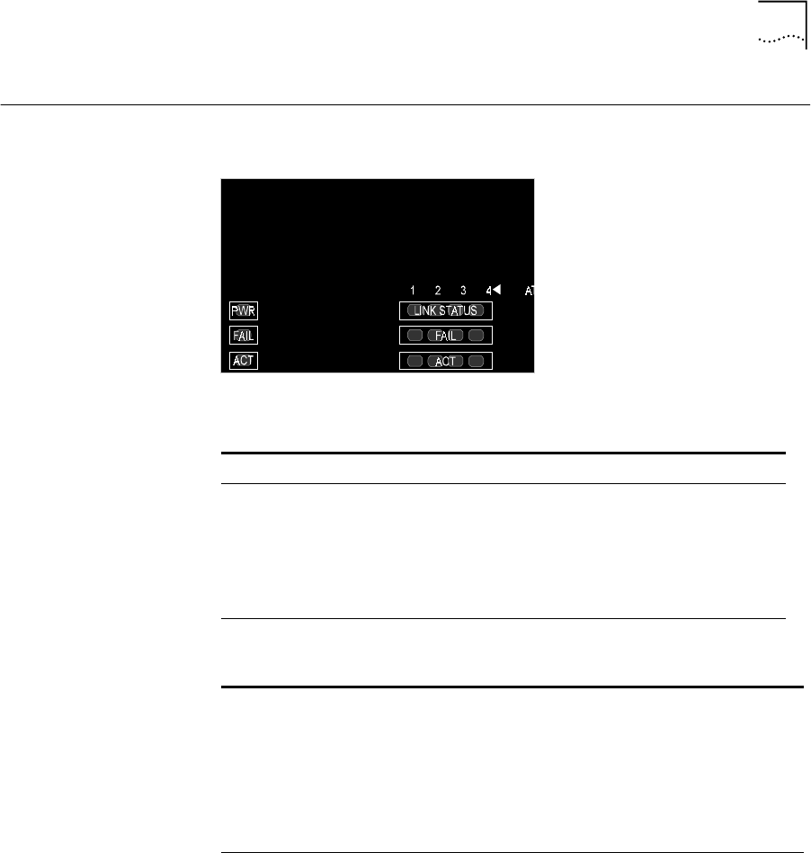
Figure 5-2 shows the 4-port interface module LEDs. Table 5-3 and
Table 5-4 list the permanent 4-port interface module panel LEDs.
Figure 5-2
Interface Module LEDs
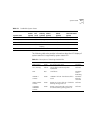
Table 5-3
Description of Interface Module LEDs
LED Color Description Source
PWR (Power) Green DC power input active. Hardware
FAIL Red CPU failure. Hardware
CPU or
Watchdog
ACT (Activity) Yellow Should blink continuously when
operational.
Software
Table 5-4
Description of Interface Module LEDs for Each Port
LED Color Description Source
LINK STATUS Green ATM physical layer is connected and
has no error.
Software
FAIL Red ATM interface port test failure. Software
ACT (Activity) Yellow Reception and transmission of cells on
ATM link – should flash to indicate
traffic.
Software