


ATM Cabling E-7
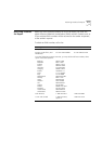
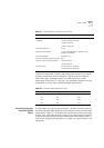
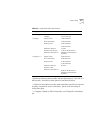
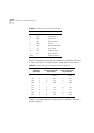
The following calculation would arrive at the link loss attenuation value
for this linked fiber (Table E-5):
Table E-5
Link Loss Attenuation Calculation
Because the resulting value, 7.85, does not exceed the maximum
attenuation value listed in Table E-1, no adjustments are needed in the
types of fibers joined or how they are connected. The link meets all of the
specifications of the MMF-PMD.
Verifying Modal
Bandwidth
The bandwidth of an optical fiber is the lowest frequency where the
magnitude of the baseband frequency response has decreased by 3 dB
compared to the magnitude at zero frequency. Bandwidth for multi-mode
fiber is referred to as modal bandwidth because it varies based on the
modal field (or core diameter) of the fiber. Modal bandwidth is specified
in units of MHz
•
km, which indicates the amount of bandwidth
supported by the fiber for a one km distance.
The modal bandwidth specified in Table E-1 is 500 MHz
•
km, which
allows the cable plant to support end-to-end bandwidth of 250 MHz at
the maximum 2 km distance. As a check, use the following formula to
verify that the bandwidth of the fiber is within an acceptable range:
n MHz
•
km / xkm = y MHz
In this formula,
n
is the amount of bandwidth available according to the
fiber specification. Divide this number by the total length
x
of the fiber in
kilometers. The result is the modal bandwidth
y
, measured in MHz.
If the result is lower than 250 MHz, the link may increase bit errors. To
reduce the likelihood of bit errors, shorten the length of the fiber or use
different fiber until the result of the calculation reaches 250 MHz.
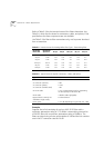
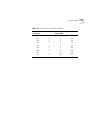
Example.
Cable with a modal bandwidth of 500
MHz
•
km will have 250
MHz of bandwidth at 2 km:
62.5µm
cable loss
+ 50µm
cable loss
+ splice
loss
+ ST con-
nector loss
+ insertion
loss
*
*for mating unlike fiber types
= Total link
attenuation
1 km(1.75
dB/km)
+1 km(3
dB/km)
+0.3 dB +0.6 dB +2.2 dB =7.85 dB