


System States
5-3
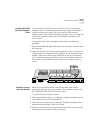
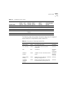
The following table also provides information about the LED display of
system states but is organized by system status LED.
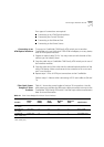
Table 5-1
CoreBuilder System States
System State
Power
(green)
Fail
(red)
Activity
(yellow)
10BASE-T
Status
(green)
Service Port
Status
(green)
Control
Terminal Status
(green)
Power-on On Off On On Flashing Flashing
Normal operation On Off Flashing On On On
Hardware fault On On Off Off Off Off
Software fault On Off Not
flashing
Undetermined Undetermined Undetermined
No power to unit Off Off Off Off Off Off
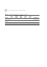
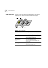
Table 5-2
Description of Switching Module LEDs
LED Color Description Source
PWR (Power) Green DC power input active. Hardware
ACT (Activity) Yellow Should blink continuously when
operational.
Software
FAIL Red CPU failure. Hardware
CPU or
Watchdog
10BASE-T
STATUS
Green 10BASE-T link OK. The Ethernet link is
active.
Hardware
Ethernet
controller
SERVICE PORT
STATUS
Green RS232 service port link OK – should be
blinking during power on.
Software
CONTROL
TERMINAL
STATUS
Green RS232 control terminal port link OK –
should be blinking during power on.
Software