


5-4
C
HAPTER
5: P
OWER
-O
N
System Power-on
This section describes the stages of system power-on of the CoreBuilder
7000 family ATM switch.
Software Loading
and Diagnostics
Apply electrical power to the system by inserting the power cord in the
power supply unit. The power supply indicator lights and the CoreBuilder
7000 family ATM switch automatically runs diagnostic software. This
software verifies that every component in the system is fully functional
before the system becomes active on the network. Diagnostics should
take sixty seconds or less.
If any component fails power-on diagnostics, the system either fails to
power on or it keeps faulty modules off-line. Once the system comes up,
you can check to see which modules, if any, have failed diagnostics by
checking the LED panels; in-depth information is available by viewing the
system configuration screens on the administration console.
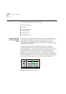
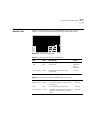
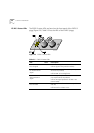
Indicators All interface and switching unit indicators light at the start of the
power-on diagnostic sequence, then go out briefly. General activity LEDs
light up as the system checks the switching and interface modules.
Finally, individual port indicators go on as the system discovers active
connections residing on the interface modules. The 10BaseT indicator on
the interface module is on during normal function, even if there is no
active 10BaseT management link.