


E-12
A
PPENDIX
E: C
ABLING
R
EQUIREMENTS
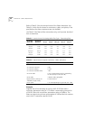
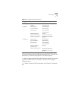
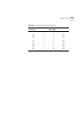
Table E-9 correlates the cable pinouts between the CoreBuilder 7000 and
a 9-pin and 25-pin PC-AT serial interface. Unspecified pins are unused.
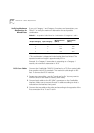
Table E-10 correlates cable pinouts between the CoreBuilder 7000 and a
modem interface.
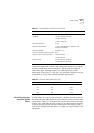
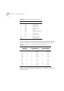
Table E-8
Serial Port Pinout and Their Functions
Pin Signal Meaning
1 RTS Request to Send
2 TxD Transmit Data
3 RxD Receive Data
4 DSR Data Set Ready
5 GND Ground
6 DTR Data Terminal Ready
7 CTS Clear to Send
8 RTS Request to Send
9 NC Not Connected
Shell Protective Ground
Table E-9
Cable Pinouts To a 9-Pin and 25-Pin Serial Interfaces
CoreBuilder 7000
Serial Port
9-pin Male
To PC-AT Serial Port
9-pin Female
To PC-AT Serial Port
25-pin Female
Screen Shell Shell Only req. if
screen
Shell Only req. if
screen
TxD 2 2 RxD 3 RxD
RxD 3 3 TxD 2 TxD
GND 5 5 GND 7 GND
RTS 1
CTS 7 7 RTS 4 RTS
RTS 8 8 STS 5 CTS
DSR 4 4 DTR 20 DTR
DTR 6 6 DSR 6 DSR