Component Summary 1-3
Component
Summary
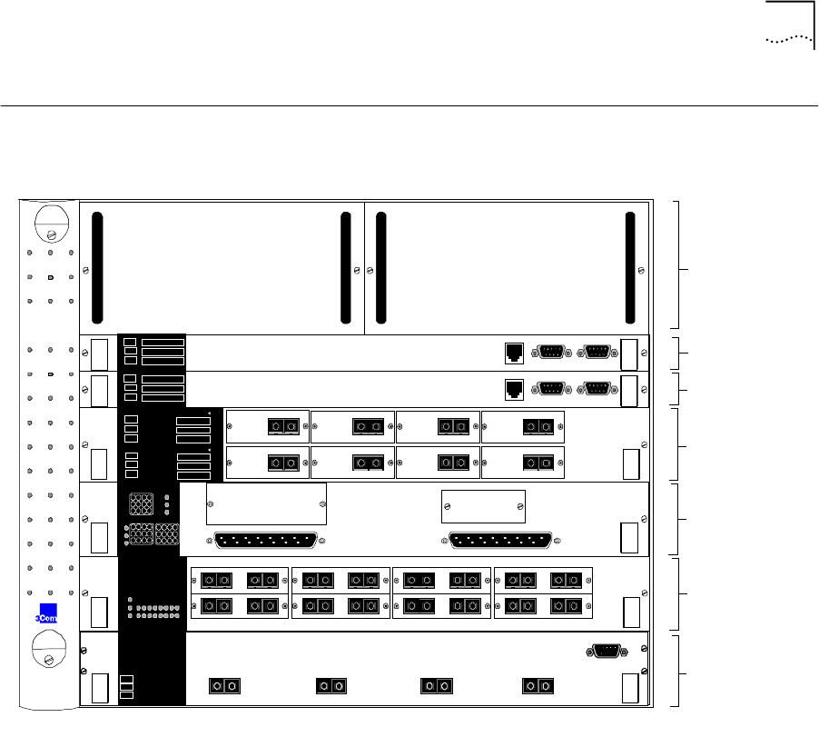
Figure 1-1 shows the components of the CoreBuilder 7000 family ATM
switch.
Figure 1-1
Components of the CoreBuilder 7000 Family ATM Switch
Enclosure
The housing for the CoreBuilder 7000 family ATM switch contains 2 slots
for switching modules and 4 slots for interface cards, 2 places for power
supplies and a ventilator fan tray. The high speed ATM switching
backplane is located inside the back of the surrounding enclosure.
Power Supply
Located at the top of the front panel. The unit is switched on and off
simply by connecting and disconnecting the power cord on the face of
the power supply unit. A second power supply may be installed for
redundancy.
7000
CoreBuilder
TM
FAIL
ACT
Control Status
10B AS E-T Status
Service
Status
PW R
HD
Management Service Port
10Base-T
RS232 RS232
Control Terminal
7000 HD
32 x 32
SWITCH
FAIL
ACT
Control Status
10B AS E-T Status
Service
Status
PW R
HD
Management Service Port
10Base-T
RS232 RS232
Control Terminal
7000 HD
32 x 32
SWITCH
7800 Gig abit
Ethernet
I/F card
4
1000 BASE-SX
1
1000 BASE-SX
2
1000 BASE-SX
3
1000 BASE-SX
SY S
ACT
FAIL
PW R
12 43
1 2 43
5 6 87
RX TX
MM
RX TX
100 FX
RX TX
MM
RX TX
100 FX
RX TX
MM
RX TX
100 FX
RX TX
MM
RX TX
100 FX
RX TX
MM
RX TX
100 FX
RX TX
MM
RX TX
100 FX
RX TX
MM
RX TX
100 FX
RX TX
MM
RX TX
100 FX
910111213141516
SYS
1 2 3 4 5 6 7 8
P
F
A
7600 Fast E th
I/F Card
A 1-12 B 13-24
7400 E th/ATM
I/F Card
ATM
SYS
AB
L
F
A
P
F
A
C
1 2 43
5 6 8
7
RX TX
OC-3MM
RX TX
OC-3MM
RX
TX
OC-3MM
RX TX
OC-3MM
RX TX
OC-3MM
RX TX
OC-3MM
RX TX
OC-3MM
RX
TX
OC-3MM
8 AT M
Port Module
Link Status
Act
Fail
PWR
FAIL
ACT
12 43
ATM
Link Status
Act
Fail
PWR
FAIL
ACT
56 87
ATM
Power Supplies
CB7000HD
Switch Module
CB7000HD
Switch Module
8 Port Board ATM
Interface Module
CB7400 ATM/Eth
Interface Module
CB7600 Fast Eth
Interface Module
CB7800 Giga Eth
Interface Module


