


4-4
C
HAPTER
4: I
NSTALLING
AND
C
ONNECTING
C
ORE
B
UILDER
M
ODULES
5
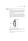
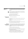
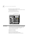
Orient the power supply so its labelling is upright.
6
Insert the power supply into the chassis by placing it between the guides
of the slot and sliding it until it stops.
7
Tighten the power supply’s securing screws.
8
Connect the power cord to the power supply.
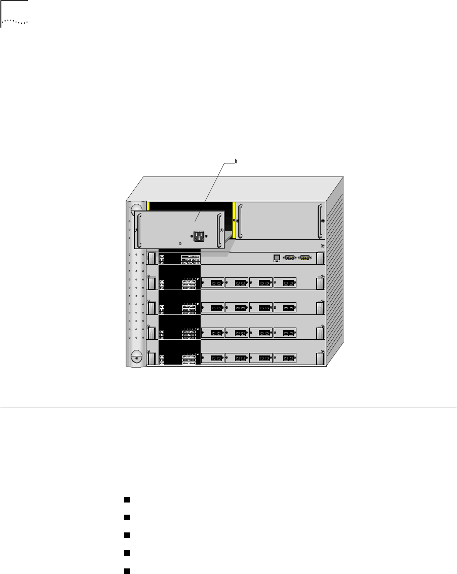
Figure 4-1
Hot-Swapping a Redundant Power Supply
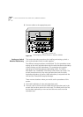
Switch Module The CoreBuilder 7000 family ATM switch provides for a redundant switch
module to ensure continued operation should the main switch module
fail. For more information on the operation of the redundant switch
module, see “Redundant Switching Module” on page 7-9.
This section includes the following topics:
Installing a Switch Module
Replacing a Switch Module
Setting up Switch Module Redundancy
Setting up Switch Module Hardware Redundancy
Setting up Switch Module Redundancy and LANE Redundancy
Inserting the power supply