


1-4
C
HAPTER
1: O
VERVIEW
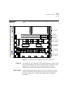
Switching Module
The two slots just under the power supply contain switching modules,
one slot for the active switching module and one slot for the redundant
switching module.
The switching module is the core switching engine of the CoreBuilder
7000 family ATM switch, controlling and monitoring passive backplane
and ATM activity. The switching module has a control port for connection
to a terminal, a management port for connection to a network
management station, and a service port for use by 3Com technicians.
Interface Module
The next four slots contain interface modules. These can be of many
different types; some are shown in the figure (see the
CoreBuilder 7000
Family ATM Switches User Guide
for details).
Fans
For ventilation a fan tray with 6 fans is located at the left side of the unit.
Installing the
CoreBuilder 7000
Family ATM Switch
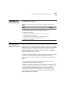
You install the CoreBuilder 7000 family ATM switch in the stages shown
Ta bl e 1- 1 .
Table 1-1
Installing the CoreBuilder 7000 Family ATM Switch
Installation Stage Chapter
1
Unpacking the CoreBuilder 7000 family ATM switch
2
2
Installing the CoreBuilder 7000 family ATM switch chassis
either on table-top or in a distribution rack
4
3
Installing a main and redundant power supply module in the
CoreBuilder 7000 family ATM switch chassis
5
4
Installing a main and redundant switch module in the
CoreBuilder 7000 family ATM switch chassis
5
5
Setting up switch module hardware redundancy and LANE
redundancy
5
6
Installing 4-Port interface modules in the CoreBuilder 7000
family ATM switch chassis
5
7
Installing or replacing other interface modules in the
CoreBuilder 7000 family ATM switch chassis
See respective
manual
8
Installing or replacing the fan tray
5
9
Connecting to network devices, ATM optical interface,
control terminal, Ethernet port and power source
5