


ATM Cabling E-5
*Maximum attenuation includes cable attenuation and the loss induced
by other components such as connectors, splices, and the mating of
unlike fiber types. Although some 2 km cable plants have a total
attenuation of less than 11.0 dB, the 2 km interstation distance must be
maintained to comply with modal bandwidth requirements.
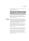
Calculating Insertion
Losses for Unlike
Fibers
If unlike fibers are mated in the cable plant, calculate insertion losses to
be certain that the cable plant does not exceed the maximum attenuation
value listed in Table E-1. To calculate the insertion loss, consider the types
of fiber in the cable plant and the connectors or splices used to join them.
Compare the result to the maximum attenuation value listed in Table E-1.
If the result is greater than the value in the table, use only like fibers in the
cable plant.
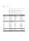
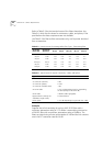
Table E-1
Standard Multi-mode Fiber Specification
Specification Description
Core 62.5 µm diameter
Cladding 125 µm diameter nominal
122 µm minimum
128 µm maximum
Numerical aperture 0.275
Maximum attenuation 11 dB* (1dB allowed for reflection and
dispersion penalties.)
Modal bandwidth 500 MHz. km
Maximum distance between nodes 2 km
Output power (from transmitter) 19 dB minimum
14 dB maximum
Receive power 30 dB minimum sensitivity
14 dB maximum sensitivity
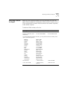
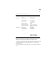
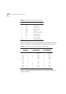
Table E-2
Alternate Multi-mode Fiber Types
Core (µm) Cladding (µm) Numerical Aperture
50 125 0.20
50 125 0.22
85 125 0.28
100 140 0.29