


5-2
C
HAPTER
5: P
OWER
-O
N
System States
This section describes the different system states of the 8-Port Board and
how they are indicated on the LED display.
The system states are:
Power-on
Normal operation
Hardware fault
Software fault
No power to unit
System States and
Switching Module
LEDs
LED indicators are located on the front panels of the CoreBuilder 7000, its
power supply, switching modules, and interface modules. These LEDs
indicate the current system state of the CoreBuilder unit and its
components. Front panel LEDs can be extremely useful in determining the
cause of specific problems.
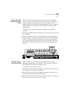
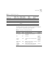
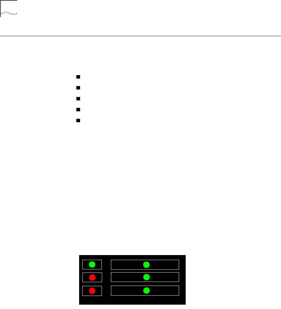
The system state in which the CoreBuilder 7000 unit is currently
operating is displayed by the switching module system status LEDs.
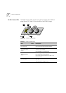
Referring to Figure 5-1, these are the three LEDs: PWR, FAIL, and ACT(ive)
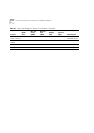
on the left side of the LED panel. Table 5-1 shows the correlation
between the current system state and SYS LEDs display. For example,
during normal operation the PWR LED is on, the FAIL LED is off and the
ACT LED is flashing. The LEDs on the right side of the panel indicate the
status of the Ethernet port, the Service port and the Control port.
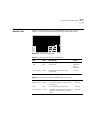
Figure 5-1
Switching Module LEDs
Control
10BASE-T
Status
Service
Status
Status
PWR
ACT
FAIL