


Chapter 3 Hardware Overview
MGS3700-12C User’s Guide
43
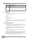
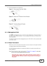
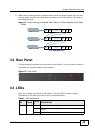
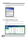
2 When daisy-chaining further Switches ensure that the signal output pins you use
are the same as those you used when connecting to the first switch, as shown in
the diagram below.
Figure 15 Daisy-chaining an External Alarm Sensor to Other Switches of the Same
Model
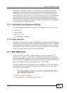
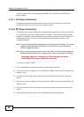
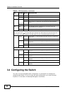
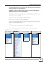
3.2 Rear Panel
The following figures show the rear panels of the Switch. The rear panel contains a
connector for external backup power supply.
Figure 16 Rear Panel
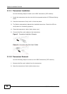
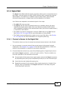
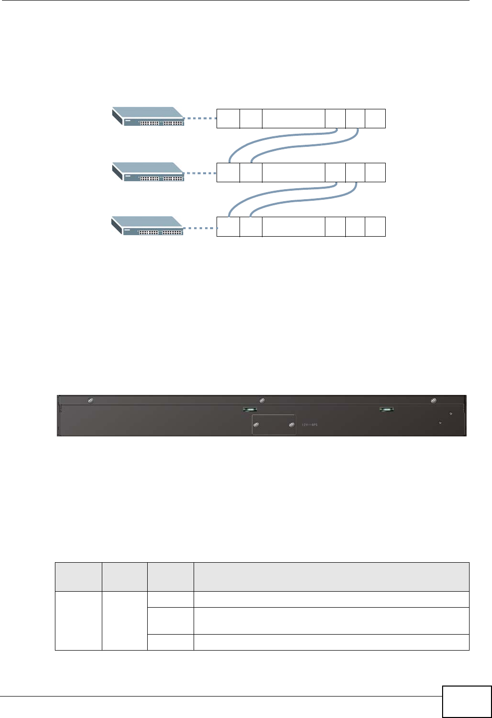
3.3 LEDs
After you connect the power to the Switch, view the LEDs to ensure proper
functioning of the Switch and as an aid in troubleshooting.
12311 10
.........
12311 10
.........
12311 10
.........
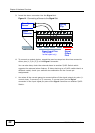
Pin Assignments
Table 2 LED Descriptions
LED COLOR
STATU
S
DESCRIPTION
BPS Green On The backup power supply is connected and active.
Blinking The system is receiving power from the backup power
supply.
Off The backup power supply is not ready or not active.