


FORM 50.40-OM2
91YORK INTERNATIONAL
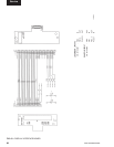
KEYPAD
(REFER TO FIGURES 45 & 46)
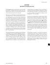
The Keypad contains touch-sensitive keys that allow
the Operator to interface with the Control Center. The
Operator presses the keys to request the desired screens
of information and enter System Setpoints.
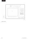
The top layer of the Keypad contains embossed areas
identifying the keys. Under each embossed key area are
two conductors, one on top of the other, separated by
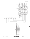
an air space. The conductors are arranged in a matrix
of rows and columns and connected to the Keypad
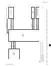
connector as shown in Fig. 46. The embossed area
of each key is located directly over the intersection
point of the conductors. Pressing the embossed key
area causes contact and electrical continuity between
the two conductors. For example, pressing the “1” key
creates continuity between the Keypad connector pin
5 (column 3) and pin 13 (row 4). Since this connector
is interfaced to the Microboard (J18), the Microboard
senses this continuity as described below and concludes
the “1” key is pressed.
The Microboard Program continuously scans the Keypad
to determine if a key is pressed. Beginning with row 1
and proceeding through all rows, the Program places a
“logic low” (<1VDC) on a row, a “logic high” (>4VDC)
on the remaining rows and reads the columns. A logic
low in any column indicates a key in that column and
row is pressed. For example, if at the time row 4 is
being driven low, if column 3 is low, then the Micro
concludes the key at coordinate of row 4 and column 3
is pressed. Since the coordinates of all keys are stored
in the Microboard’s Program, it can identify which key
is at this coordinate and responds accordingly. In this
example the “1” key is pressed.
In order for the Microboard to reliably detect closed
and open keys, each key must meet a closed circuit
and open circuit resistance requirement. When a key
is pressed, the contact resistance must be < 100 Ohms.
When a key is not pressed, the contact resistance must
be > 1 Meg Ohm. If the Microboard is not responding to
a pressed key, or if it’s detecting a closed key when none
are pressed, it could be because the contact resistance
requirements are not being met. The operation of each
key can be checked with an Ohmmeter. To check the
open and closed contact resistance of any key, refer
to the “Diagnostics and Troubleshooting” description
in this book.
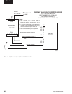
The Keypad is attached to the front of the Remote
Control Center door with an adhesive backing. If
service replacement is required, start at one corner
and slowly peel the Keypad from the door. The rear
side of the replacement Keypad is coated with an
adhesive covered with a paper backing. Remove the
paper backing, align the Display opening and apply
the Keypad to the door.
5