


YORK INTERNATIONAL106
SECTION 6 – PART NUMBER AND RENEWAL PARTS
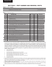
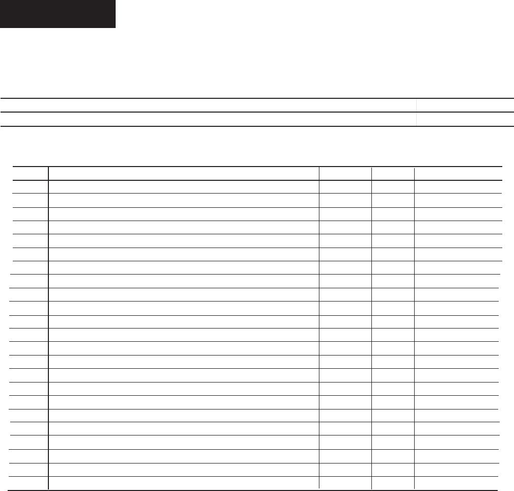
ITEM DESCRIPTION FIG. NO. QTY. PART NO.
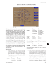
1 MICROPROCESSOR BOARD (NOTE 2) 56 1 031-01730-002
2 POWER SUPPLY ASSY 56 1 371-02750-411
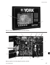
3 KEYPAD 55 1 024-30974-001
4 TERMINAL BLOCK 56 1 025-35120-000
5 DISPLAY KIT (NOTE 1) 55 1 331-02053-000
6 CABLE ASSY. POWER SUPPLY 56 1 571-02750-421
7 KEYPAD TO MICRO RIBBON CABLE 56 1 031-02056-000
8 EPROM, BIOS (U45) 56 1 031-01796-001
9 FLASH MEMORY CARD, PROGRAMMED (U46) 56 1 031-02057-001
10 IC, BRAM (U52) 56 1 031-02028-000
11 FLAT CABLE FERRITE CLAMP 56 1 025-34172-000
12 SLEEVE SNAP FERRITE 56 1 025-35154-000
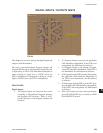
13 BACKLIGHT BULB 57 1 See Note 4
14 BACKLIGHT INVERTER BOARD 57 1 See Note 4
15 BACKLIGHT INVERTER BOARD RIBBON CABLE 57 1 See Note 4
16 DISPLAY INTERFACE BOARD 57 1 See Note 4
17 DISPLAY INTERFACE BOARD RIBBON CABLE 57 1 031-02055-000
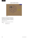
18 LAN TRANSIENT PROTECTION MODULE 2 1 031-01586-000
19 TRANSIENT VOLTAGE SUPPRESSOR 2 2 031-02076-000
20 IC, RS-485 DRIVER 56 4 031-02074-000
21 FUSE, F1 & F2, 5 AMP (Rev. E and later Microboards) 58 2 025-34592-000
22 MICROGATEWAY OPTIVIEW KIT (future option) 56 1 371-03609-001
23 EPROM, MICROGATEWAY 56 1 See 450.RP1
TABLE 5 - RENEWAL PARTS
NOTES:
1. The replacement Liquid Crystal Display supplied by YORK might not be by the same manufacturer as the original Display. Each Display
requires a specific Display Interface Board (Item 16), Backlight Inverter Board (Item 14), and Backlight Inverter Board ribbon cable (Item
15). Therefore, the Liquid Crystal Display is not available separately. Service replacement Displays or supporting components must
not be arbitrarily selected! Non-compatibility of components will result in incorrect operation! To assure compatible supporting
components, the Display is supplied as a kit (part number 331-02053-000), which contains a replacement Display and all compatible
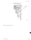
supporting components on a mounting plate. For future reference, a label attached to the side of the mounting plate (Fig. 57) lists
the YORK part numbers of these compatible components and the required configuration of the Microboard Program Jumpers. These
Program Jumpers must be configured for this Display by a qualified Service Technician following instructions in this manual. The
contents of the kit are as follows:
a. Liquid Crystal Display
b. Backlight Bulb (Item 13)
c. Appropriate Display Interface Board (Item 16) for Display
d. Appropriate Display Interface Board ribbon cable (Item 17) for Item16.
e. Appropriate Backlight Inverter Board (Item 14) for Display.
f. Appropriate Backlight Inverter Board ribbon cable (Item 15) for Item 14.
g. All mounting hardware.
h. Installation instructions.
2. Replacement Microboards are shipped without Flash Memory Cards (U46) or BRAM (U52). Remove these devices from defective Board
and use them in replacement Board. If a new Eprom, Flash Memory Card or BRAM is required, refer to the previous table for part number.
Return all unused Flash Memory Cards with Warranty return boards.
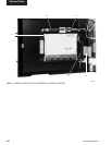
3. Ferrites are shipped in cloth bag. They are applied to the chiller communication RS-485 cable and the MicroGateway LAN cable prior
to exiting the Remote Control Center enclosure.
4. Refer to label (Fig. 57) on Display mounting plate for YORK part number of applicable replacement part. Service replacement Display
supporting components must not be arbitrarily selected! Non-compatibility of components will result in incorrect operation!
Renewal Parts
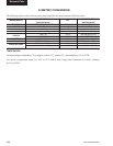
TABLE 4 - PART NUMBER
DESCRIPTION PART NO.
COMPLETE OPTIVIEW RCC PANEL 371-02750-101