


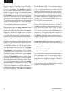

YORK INTERNATIONAL68
MICROBOARD
(REFER TO FIG. 31 - 36)
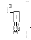
The Microboard contains the operating software
(Program), microprocessor (Micro), and supporting
circuits for the Micro.
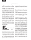
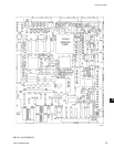
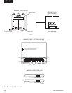
The Program is a set of instructions to control remote
chillers and the display. It also contains the Display
messages and screens. It is stored in a memory device
called a ash memory card. This is a type of nonvolatile
memory that can be read from or written to, but requires
the locations to be erased before they are written to. With
the exception of a write/read sequence that occurs during
the Boot-up process explained below, this device is used
primarily as read-only in this application. A write protect
switch is located on the left edge of the card as shown in
Fig. 32. It must be placed in the “Write Enabled” position
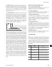
in order to allow successful Boot-up. The card is located
in socket location U46 (Ref. Fig. 31). It connects to the
Board via an Elastomeric connector that is a silicon rubber
strip embedded with silver conductors. The Card can
be removed from its socket by using the thumb to press
down on the socket’s plastic tension spring. The card
is installed by inserting it into the socket/holder and
pressing on the surface of the Card until it snaps into
place. The Memory card is a replaceable component.
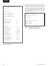
Refer to the YORK Renewal Parts List. The version of
the Memory card is an alphanumeric code that represents
the application and revision level. The version is printed
on a label adhered to the memory card’s surface. The
version code is as follows:
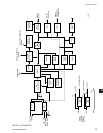
The Micro monitors and controls the chiller by reading
and executing the Program instructions in a sequence
determined by the Program. Under Program control, the
Micro communicates with the chillers via RS-485 serial
communications to determine the operating conditions.
As operating conditions require, status messages are
retrieved and displayed. The Keypad is read as Digital
Inputs. When an operator presses a key to request a
display, the Micro interprets the request, retrieves the
display from the Program and displays it. The Program
assembles data in the correct format for transmission
through the Serial Data Ports to the chiller(s) and
peripheral devices. The Program also instructs the Micro
to respond to requests from peripheral devices for serial
data transmissions.
The Mux (multiplexer) is a switching device that only
allows one analog input through at a time. The inputs
are selected sequentially by the Micro per Program
instructions.
The A/D Converter converts each analog input to a
12-bit word. In this form, the values can be stored in
memory devices, compared to values in the Program,
transmitted through Serial Ports or sent to the Display
Controller for display. Control signals to start conversion
process are from the Micro via the FPGA.
The Watchdog circuit monitors the +5VDC supply from
the Power Supply to determine when a power failure is
occurring. Just prior to the supply decreasing to a level
where the Micro and supporting circuits can no longer
operate, it applies a reset signal to the Micro. The Micro
responds by shutting down the remote control center and
retrieving the Power Failure message from the Program
and sending it to the Display Controller for display.
Similarly, when power is first applied after a power
failure, it maintains the Micro in a reset state until the
+5VDC has returned to a sufcient level. The Watchdog
circuit also assures that all the Program instructions are
being performed and that the Program has not latched-up,
bypassing important safety thresholds. If the Program
has latched-up, the Micro displays WATCHDOG –
SOFTWARE REBOOT message.
The Program Jumpers (Table 2) and Program Switches
(Table 3) are used to alter the Program operation or
congure the Microboard hardware for specic operation.
This allows the Program and Microboard to be universal
for all applications. Refer to Table 2 and 3 for the function
of each jumper and switch. The position of some can be
determined and set by the Service Technician to meet the
desired operation. The position of others is dictated by the
size, type or style of certain Control Center components
and thus the position is determined by the YORK Factory.
The required position of each is listed in these tables. The
Program Jumpers are wire bridges that are either left in
place or cut. The Program Switches are miniature switches
that are placed in either the ON or OFF position.
C. RCC. 01. XX.
Revision level. Increments 00, 01 etc.
Product Code for OptiView RCC
Remote Control Center
Commercial
Service