


YORK INTERNATIONAL60
PRINTERS
A printer can be connected to the OptiView Remote
Control Center’s Microboard to print the following
reports. The screen from which each report can be
generated is listed in parenthesis.
• Operating Data - Present system parameters
(Unit)
• History - System parameters at the time of the
last fault while running and last saved faults
(History)
The printer can be permanently connected to the Remote
Control Center or connected as required to produce a
report. If permanently connected, a DATA LOGGING
feature can produce a Status report automatically,
beginning at an Operator selected start time and occurring
at an Operator selected interval thereafter.
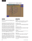
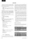
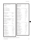
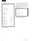
The following gures are examples of the different
print reports.
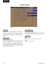
• Figure 28 - Operating Data
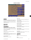
• Figure 29 - History (Header)
PRINTERS
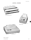
The following Printers can be used. Printers must be
equipped with an RS-232 Serial interface.
• Okidata –
Models: 182,182 turbo, 184 turbo
Dimensions: 14 in. wide x 10.5 in. deep
Paper: 8.5 in. wide
Type: Dot matrix impact
• Weigh-Tronix –
Models: 2600, 1220
Dimensions: 2.3 in. wide x 2.8 in. deep
Paper: 2.25 in. wide
Type: Dot matrix impact
• Seiko –
Model: DPU414-30B (Power supply PW4007-U
I required)
Dimensions: 6.3 in. wide x 6.7 in. deep
Paper: 4.4 in. wide
Type: Thermal
Purchase: Contact your local
YORK Service Ofce
The OptiView Remote Control Center provides the
required formatting control codes for the printers above
when the printer is selected on the PRINTER Screen
in the instructions below. These codes are transmitted
through the serial interface to the printer to provide a
proper print format. Different printers require different
formatting control codes. Other printers might provide
proper operation when connected to the OptiView
Remote Control Center. However, the print format
may not be correct or as desired. Proceed with caution
and use the following guidelines if an unlisted printer
is selected:
1. All must be capable of RS-232 Serial communications.
2. Primary differences between printers involve the
formatting control codes required by the printer.
These codes are sent from the Control Center to
the printer. For example, Weigh-Tronix printers
require a control code to select 40 column width.
This same code is interpreted by the Okidata printer
as an instruction to print wide characters. In some
instances, a printer will ignore a code it cannot
interpret.
3. The OptiView Remote Control Center requires
a busy signal from the printer when the printer
receive buffer is full. This causes the OptiView
Remote Control Center to momentarily terminate
data transmission until the printer can accept more
data. The busy signal polarity must be asserted
low when busy.
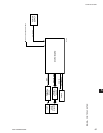
PRINTER CONNECTIONS
Connect the printers to the Control Center Microboard as
follows. Only one printer can be connected at a time.
• OKIDATA 182, 182 turbo, 184 turbo
Microboard Printer Function
J2-4 pin 3 Tx (data to printer)
J2-2 pin 11 DSR (busy signal from printer)
J2-9 pin 7 Gnd
Cabinet shield
• WEIGH-TRONIX
Microboard Printer Function
J2-4 pin 2 Tx (data to printer)
J2-2 pin 5 DSR (busy signal from printer)
J2-9 pin 7 Gnd
Cabinet shield
Printers