


FORM 50.40-OM2
101YORK INTERNATIONAL
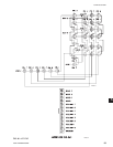
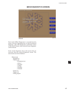
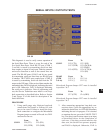
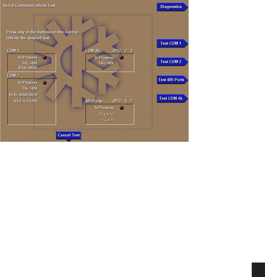
SERIAL INPUTS / OUTPUTS TESTS
This diagnostic is used to verify correct operation of
the Serial Data Ports. There is a test for each of the
five Serial Data Ports. Each RS-232 port (COM 1,
2 and 4b) is tested by transmitting serial test data
from outputs to inputs of each port. Both the transmit
and receive functions as well as the control lines are
tested. The RS-485 ports (COM 3 and 4a) are tested
by transmitting serial test data from one RS-485 port
to another. The TX/RX opto-coupled port (COM 5)
is tested by transmitting serial test data from the TX
output to the RX input. If the received data matches the
transmitted data, PASS is displayed, indicating the serial
port is OK. Otherwise, FAIL is displayed, indicating
the serial port is defective. Prior to performing each
test, the Service Technician must install a wire loop-
back connection as described below. Refer to Section
5 and Figure 35 of this book for description of the
Serial data Ports.
PROCEDURE
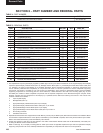
1. Using small gauge wire, fabricate loop-back
connections and install as follows for each
port to be tested. Failure to install the loop-
back connection or congure the Microboard
Program jumper as noted will result in a FAIL
outcome for the test.
From To
COM 1 J2-4 (TX) J2-3 (RX)
J2-5 (DTR) J2-2 (DSR)
From To
COM 2 J13-5 (TX) J13-3 (RX)
J13-7 (DTR) J13-1(DCD) &
J13-2(DSR)
J13-4 (RTS) J13-6 (CTS) &
J13-8 (RI)
RS-485 From To
(COM J12-3 (+) J11-3 (+)
3 & 4a) J12-2 (-) J11-2 (-)
Microboard Program Jumper JP27 must be installed
in position 1 & 2.
From To
COM 4b J2-7 (GTX) J2-6 (GRX)
Microboard Program Jumper JP27 must be installed
in position 2 & 3
2. After connecting appropriate loop-back con-
nections above, press the appropriate key to
initiate the desired test. An LED will illuminate
indicating the test is in progress. If it is desired
to terminate the test, press the CANCEL TEST
key. Test data is sent from an output to an input
as described below. At the completion of
each test, if the data received matches the
data sent, the Serial Port operates properly
and PASS is displayed. Otherwise, FAIL is
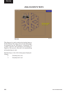
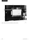
FIG. 52
00530VIPC
5