


YORK INTERNATIONAL82
to the next HSYNC pulse. All YORK applications
operate in the DISPLAY ENABLE mode. The state of
the ENABLE (Display Interface Board J1-27) signal
from the Microboard places the Display in the desired
mode as follows:
• LG SEMICON Display does not have the xed
mode feature.
As described above, in OptiView Control Center
applications, the Display scan is left to right, beginning
with the top row and continuing sequentially through the
rows to the last row. However, in Display applications
other than OptiView Control Centers, image reversal is
sometimes required. In image reversal applications, the
scan is reversed; the scan is right to left, beginning with
the last row and proceeding to the top row.
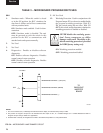
Displays by different manufacturers can require
different timing and control signals. The Microboard
must know which Display is present in order to provide
the correct signals. Therefore, when AC control power
is rst applied to the OptiView Control Center, as part
of the power-up sequence, the Microboard reads the
Panel ID wire jumpers P1D0 - P1D3 on the Display
Interface Board and determines which Display is
present. It can then provide the correct timing and
control signals to produce the graphic image, as
required by the Display manufacturer. Since the
Display Interface Board identies the Display for
the Microboard, there is a different Display Interface
Board required for each Display application and each
has a unique jumper conguration that identies the
Display. A complete explanation of this process is
included in the preceding “Microboard” description
and the “Display Interface Board” description that
follows.
The DC power source to operate the Display is provided
by the Microboard J5. Some Display manufacturers
require +5VDC; others require +3.3VDC. The position
of Microboard Program Jumper JP2 determines which of
these power sources is supplied to the Display. JP2 must
be positioned according to the Display manufacturers
requirements. Refer to Table 2, “Program Jumpers”.
The Backlight Lamp provides the illumination for the
display. Average lamp life is 25000 hours (2.9 years).
Some displays use one lamp. Others use two lamps.
Lamps are replaceable, but not interchangeable between
different displays. Each Display manufacturer species
the required lamp for their display. Refer to replacement
parts list for appropriate replacement lamp. Service
replacement lamps are stocked in the YORK Service Parts
Distribution Center. The lamp is illuminated by applying a
high voltage AC (500 to 1500VAC) to it. This illumination
voltage is created from a low level DC voltage (+12VDC
or +5VDC as required by the Display manufacturer) by the
Backlight Inverter Board. Lamp brightness is controlled
by varying the high voltage AC. The greater the voltage
the brighter the illumination. The lamp is controlled by
on/off commands and brightness control signals applied
to the Backlight Inverter Board from the Microboard.
The Microboard Program determines when the lamp is
turned on and off and the lamp brightness. Each Display
manufacturer species the Backlight Inverter Board
to be used. Therefore, it will vary according to the
Display manufacturer. The ribbon cable that connects the
Microboard to the Backlight Inverter Board also varies
according to the Display manufacturer’s requirements.
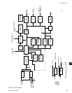
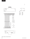
Refer to Fig. 44. Microboard Program Jumpers JP3, 4,
5, 7 and 8 determine the voltage levels of the control
signals sent to the Backlight Inverter Board and must be
congured per the Display manufacturer’s requirements as
listed in Table 2. A detailed description of the operation of
this board is in the “Backlight Inverter Board” description
that follows. Also refer to the preceding “Microboard”
description for a detailed description of the Lamp
Dimmer circuit.
The actual Display that is installed in the OptiView
Control Center of the new chiller is determined by the
Display manufacturer contractual agreement in place
during the time of OptiView Control Center production.
Displays stocked for Service replacement are a result of
that same agreement. Therefore, the Display received for
service replacement may be by a different manufacturer
than the one in the OptiView Control Center. Since
each Display manufacturer requires a specic Display
Interface Board, Backlight Inverter Board and Inverter
Ribbon Cable, replacement Displays are ordered and
supplied as a Display Replacement Kit (YORK Part
Number 331-02053-000) to assure component compat-
ibility. The items supplied in the kit are compatible with
the supplied Display. The kit consists of the following
items mounted on a Display mounting plate:
Display Replacement Kit 331-02053-000:
1. Liquid Crystal Display with Lamp
2. Appropriate Display Interface Board for item 1
3. Appropriate Backlight Inverter Board for item 1
4. Appropriate ribbon cable (Backlight Inverter Board
to Microboard) for item 1
5. Ribbon cable (Display Interface Board to
Microboard)
6. All mounting hardware
7. Installation instructions. A label attached to the
Service