


FORM 50.40-OM2
83YORK INTERNATIONAL
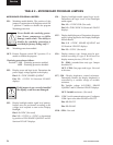
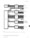
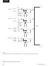
Display mounting plate lists the YORK part numbers
of the Display supporting components mounted
on the Display mounting plate and the required
Microboard Program Jumper (JP2 through 8)
congurations. Microboard Program Jumpers
JP2 - JP8 will have to be congured appropriately
for the replacement display. Refer to Table 2
“Program Jumpers”.
Display Handling:
1. The display is made of glass. It could break if
dropped.
2. The display front surface is easily scratched. If
soiled, wipe with a dry cotton cloth. Use no water
or chemicals.
3. The display is static sensitive. Electrostatic dis-
charges may damage the display.
4. A laminated lm is adhered to the display front
glass surface to prevent it from being scratched. Peel
off very slowly to prevent static damage.
Always remove control power from
the OptiView Remote Control Center
before connecting or disconnecting
wires to the display. Connecting or
disconnecting wires to the display
with power applied will damage the
display!!!
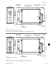
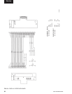
BACKLIGHT LAMP REPLACEMENT:
SHARP LQ10D367 Display: (Refer to Fig. 41)
Removal:
The Lamp slides into the Display from left to right and
is secured with a locking tab.
1. Remove Control Power from the OptiView Control
Center.
2. Remove protective cover from rear of Display.
3. Disconnect Lamp AC power connector from
Backlight Inverter Board.
4. Using ngernail or thin at blade screwdriver, bend
the locking tab outward slightly to clear the Lamp
housing protrusion.
5. Grasp Lamp AC power connector and gently pull
until Lamp housing clears locking tab.
6. Grasp Lamp housing and pull until Lamp housing is
completely removed from the Display.
Installation:
1. Slide new Lamp into Display from left to right
until Lamp housing protrusion locks into Display
locking tab.
2. Connect Lamp AC power connector to Backlight
Inverter Board.
3. Apply Control Power to OptiView Control Center.
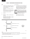
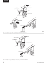
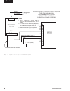
LG Semicon LP104V2 Display (refer to Fig. 42)
Removal:
The Lamp slides into the Display from left to right and
is secured with a screw.
1. Remove Control Power from the OptiView Remote
Control Center.
2. Remove protective cover from rear of Display.
3. Disconnect Lamp AC power connector from Back-
light Inverter Board.
4. Using small Phillips screwdriver, remove lamp
retaining screw.
5. Grasp Lamp AC power connector and gently pull
until Lamp housing is completely removed from
the Display.
Installation:
1. Slide new Lamp into Display from left to right until
Lamp housing is fully inserted.
2. Secure Lamp with Lamp retaining screw.
3. Connect Lamp AC power connector to Backlight
Inverter Board.
4. Apply AC power to OptiView Remote Control
Center.
5