YORK INTERNATIONAL78
5 - 11 Not Used
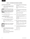
12 - Watchdog Protection -Used in conjunction with
Program Jumper JP1 (see above) to enable/disable
the program watchdog protection. With JP1
IN, this switch setting has no effect. With JP1
OUT, this switch setting determines whether the
watchdog protection is enabled or disabled.
NEVER disable the watchdog protec-
tion! Severe compressor or chiller
damage could result. The ability to dis-
able the watchdog protection is provided
for YORK factory testing only.
ON: Watchdog protection enabled.
OFF: Watchdog protection disabled.
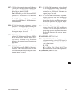
SW1
1 - Simulator mode - When this switch is closed
or in the ON position, the RCC simulates the
data from 4 chillers and will not communicate
with any attached units.
ON: Simulator mode enabled. Used for dem-
onstration.
OFF: Simulator mode is disabled. The unit
must be powered on with the switch in this
position for the RCC to communicate with
attached units and operate normally.
2 - Not Used
3 - Not Used
4 - Diagnostics - Enables or disables software
diagnostics
ON: Enables software diagnostics. Disables
normal control center operation
OFF: Disables software diagnostics. Enables
normal control center operation.
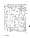
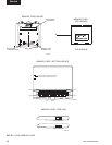
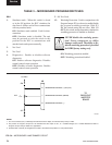
TABLE 3 – MICROBOARD PROGRAM SWITCHES
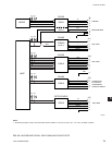
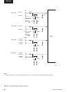
NOTES:
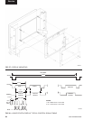
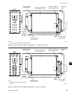
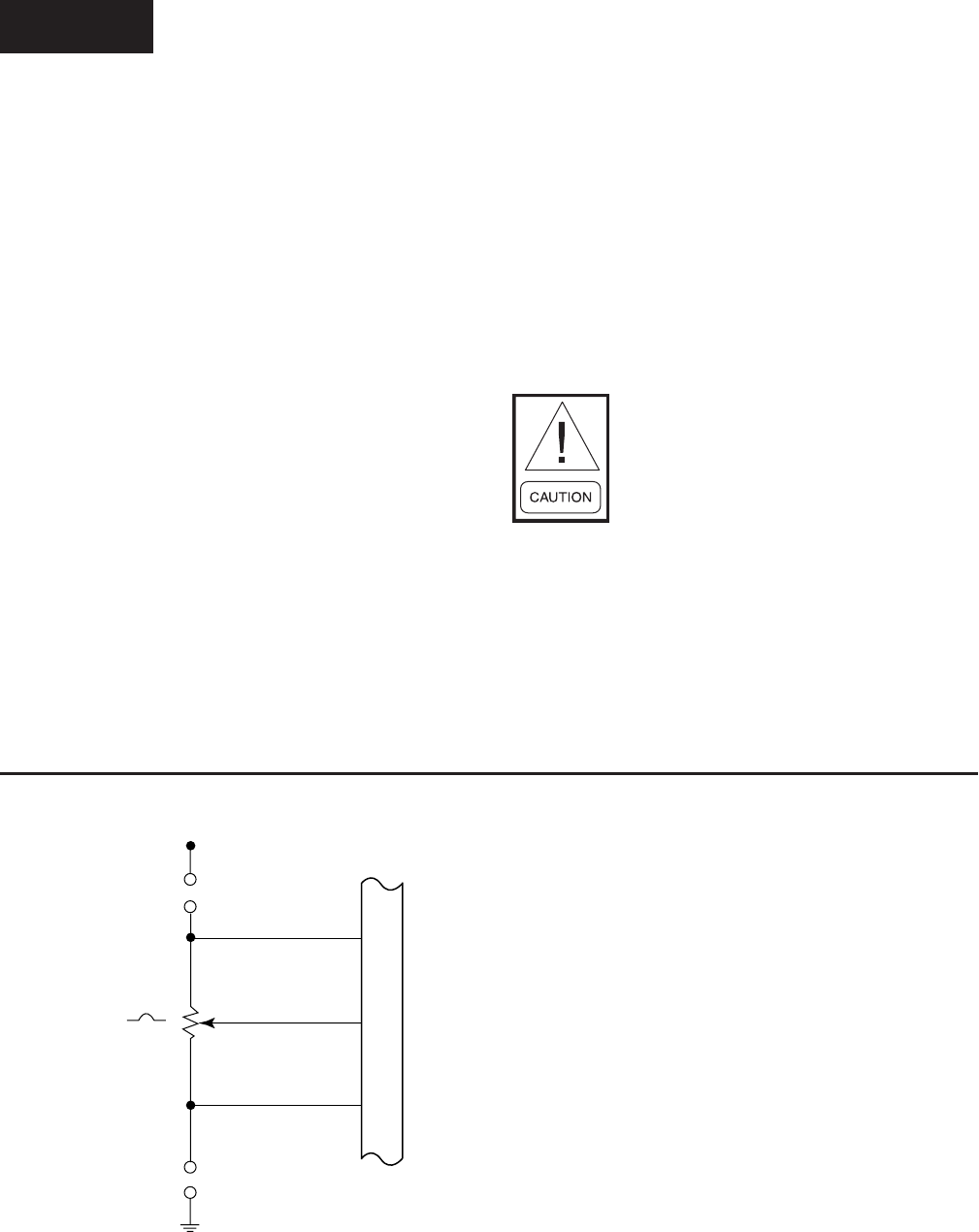
1. J6-6 not connected (N.C.) to Backlight Inverter Board when display is manufactured by Sharp or NEC.
2. The position of Program Jumpers JP7 & JP8 determine the output at J6-7; In = Variable Voltage; Out = Variable Resistance. Refer to
Program Jumper Listing in Table 2 for applications.
3. Potentiometer is actually an integrated circuit that is the electrical equivalent of a 10K potentiometer.
FIG. 34 – MICROBOARD LAMP DIMMER CIRCUIT
6
7
8
J6
BRIGHTNESS CONTROL (+) OR (N.C.)
BRIGHTNESS CONTROL (WIPER)
BRIGHTNESS CONTROL (-)
TO
BACKLIGHT
INVERTER
BOARD
JP8
JP7
5.0 VDC
10 K
LD04054
Service


