


YORK INTERNATIONAL72
Program Jumper JP5) to high voltage AC (500 to
1500VAC). This high voltage AC is applied to the lamp
to cause it to illuminate. The Backlight is turned on
and off with the “Enable Backlight” (J6-5) signal. The
position of Program Jumper JP4 determines whether
this is a +12VDC or +5VDC signal. In some displays,
the Backlight turns on when this signal transitions
from low to high; others turn on when it transitions
from high to low. The position of Program Jumper
JP3 determines the transition that will occur when the
Display Controller outputs the “Enable Backlight”
signal. Program Jumper JP3 must be positioned accord-
ing to the Display manufacturer’s requirement.
Under Program control, the Display Controller controls
the Backlight brightness via the Lamp Dimmer circuit.
In order to extend the life of the backlight lamp, the lamp
brightness is driven to 50% brightness after 10 minutes
of Keypad inactivity. At this brightness level, the Display
can still be read. Subsequently, when Keypad activity is
detected (i.e. a Keypad key is pressed), the lamp is driven
back to full brightness (100% brightness). Some display
manufacturers require a variable voltage to vary the
brightness; others require a variable resistance. Program
Jumpers JP7 and JP8 allow either method to be used.
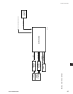
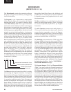
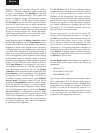
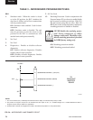
The Lamp Dimmer is an integrated circuit that is
the electrical equivalent of a 10K ohm potentiometer
with 100 positions or steps (ref. Fig. 34). The Display
Controller controls the position of the potentiometer. The
Lamp Dimmer varies the brightness of the Backlight
by applying either a variable voltage (0-5.0VDC) or
a variable resistance (0-10K ohms), to the Backlight
Inverter Board. If Program Jumpers JP7 and JP8 are
installed, the Lamp Dimmer output is a variable voltage;
if both are removed, the output is a variable resistance.
The Lamp Dimmer outputs “Brightness Control Wiper”
(J6-7) and “Brightness Control -“ (J6-8) to the Backlight
Inverter Board. If configured for variable voltage
output, the voltage between J6-7 and J6-8 can be varied
from 0 (100% brightness) to 5.0VDC (0% brightness). If
congured for variable resistance, the resistance between
J6-7 and J6-8 would vary from 0 ohms (0% brightness)
to 10K ohms (100% brightness).
The PC-104 Port (J16 & J17) is an industry standard
arrangement of two connectors that allows the stacking
of 3.6 x 3.8 inch printed circuit boards (PC-104
Modules) on the Microboard. The circuits on these
boards have access to the Microboard’s address/data bus,
and therefore become an extension of the Microboard.
This provides expansion of the Microboard’s capabili-
ties without redesigning or changing the size of the
Microboard. PC-104 Modules are not used in all
Remote Control Center applications.
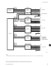
System temperatures, in the form of analog DC
voltages from temperature thermistors, are input to
the MUX (multiplexers). Under Program control, the
Micro selects these values, one at a time, for input
to the Analog to Digital (A/D) converter. As each
one is selected, it is passed to the A/D Converter for
conversion to a 12-bit digital word that is then input in
parallel form to the Micro. The Micro stores each value
in the DRAM for display requests, further processing
or Serial Port transmission. Each value is also stored in
the BRAM for History data.
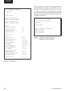
Service Replacement: Microboards are supplied as
Service Replacement parts without the following
components:
• BRAM (U52)
• Flash Memory Card (U46)
• BIOS EPROM (U45)
Upon receipt of the replacement Microboard, remove
these components from the Board being replaced
and install in the replacement Board. Although these
components have YORK Part Numbers as listed in
the Parts List and can be individually replaced, it is
recommended that these existing components be used
in the new Board since the BRAM memory device
contains all of the programmed setpoints.
Service