


FORM 50.40-OM2
65YORK INTERNATIONAL
This document explains the operation of the printed
circuit boards and major components of the OptiView
Remote Control Center to a level that allows a Service
Technician to troubleshoot and locate the source of
a problem.
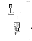
The overall system architecture is described and
illustrated with block diagrams. This describes the
general function of each component and provides the
system interface and signal ow. The function of each
component and signal ow between components must
be understood before effective troubleshooting can
commence.
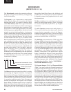
The operation of each printed circuit board is described
and illustrated with a block diagram that is a simplied
representation of board circuitry. The expected voltage
level at all inputs and outputs of each board for any
operating condition is provided.
Included in this document are procedures that have to
be performed at commissioning or during service. They
should not be performed by anyone other than a Service
Technician. For example, calibration procedures have
to be performed or veried at commissioning or when
a component is replaced. Since the operating program
supplied in each OptiView Remote Control Center is
universal to all applications, special setpoints, program
jumpers and program switches are required to congure
the OptiView Remote Control Center for this locations
operating conditions.
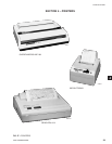
SECTION 5 – SERVICE
INTRODUCTION
A System Commissioning Checklist is provided as
reference of items to be performed during control panel
commissioning.
Diagnostic Routines allow service analysis of the
following functions:
• Display
• Analog inputs
• Dip switches and jumpers
Before beginning any troubleshooting, observe all
display messages. The conditions required to produce
the message must be clearly understood before
proceeding. (If this is not heeded, much time will
be wasted). Armed with a knowledge of the overall
system architecture and the function of each printed
circuit board and signal ow provided by this manual,
proceed with the appropriate Wiring Diagram listed
above to trace the problem through the system. Use the
Diagnostic Routines where appropriate.
5