


FORM 50.40-OM2
89YORK INTERNATIONAL
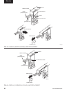
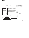
DISPLAY BACKLIGHT INVERTER BOARD
(REFER TO FIG. 44)
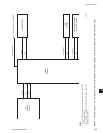
The Display Backlight Inverter Board generates a
high voltage AC signal that is applied to the backlight
lamp, causing it to illuminate. The magnitude of the
signal determines the lamp brightness. Displays by some
manufacturers have two lamps; one at the top and one at
the bottom of the display. Other Display manufacturers
have only a lamp at the top of the display.
An Inverter converts low level DC voltage (+12VDC
or +5VDC, as required by the manufacturer) from the
Microboard to a 500 to 1500VAC 60KHz signal that
is applied to the lamp. The higher the AC voltage, the
greater the brightness of the lamp. When this voltage
is not present, the lamp is turned off.
High voltage, up to 1500VAC, is pres-
ent at the output of the backlight
inverter board. Refer to Figure 44
and locate the output connectors. Use
extreme caution when working in this
area!!!
Different Display manufacturers require different Backlight
Inverter Boards. The different board designs require different
control voltage inputs. To accommodate these variations,
Microboard Program Jumpers JP3 - JP5, JP7 and JP8 must
be congured to provide the required voltage levels. A label
attached to the Display mounting plate lists the required
Program Jumper conguration for that particular display.
Refer to Table 2 for required Program Jumper congurations
for the various Display applications.
Under Program control, the Microboard generates the
control signals that are applied to the Backlight Inverter
Board. The Program determines when the lamp is turned
on and off. It also adjusts the lamp brightness. To increase
the average lamp life of 25000 hours, the lamp brightness
is normally adjusted to 50%. This brightness level will
still allow the display to be visible. When the Program
senses a Keypad key has been pressed, it adjusts the
brightness to 100% (maximum).
The lamp illumination high voltage AC is generated
from either +12VDC or +5VDC as required by the
manufacturer. Microboard Program Jumper JP5 must
be positioned to provide the required voltage. The
Microboard provides the Backlight Enable signal. This
signal turns the lamp on and off. Some manufacturers
require this signal to be +12VDC, others require +5VDC.
Program Jumper JP4 must be positioned to provide the
required voltage. Further, some applications require this
signal to be a +VDC (+12VDC or +5VDC) to turn on
the lamp. Others require this signal to be 0VDC to turn
on the lamp. Program Jumper JP3 must be positioned to
provide the required polarity.
Depending upon the Display manufacturer, the brightness
control input from the Microboard must be either a variable
voltage or a variable resistance. Microboard Program
Jumpers JP7 and JP8 are used to provide the appropriate
technique (refer to Fig. 34). The lamp dimmer circuit on
the Microboard is an IC that is the electrical equivalent
of a 10K ohm potentiometer with 100 positions or steps.
The Program adjusts the position of the potentiometer.
When congured for variable voltage (JP7 & JP8 installed),
the output between Microboard J6-7 and J6-8 is a 0 to
+5.0VDC signal. Not all applications require the full
5.0VDC range. If congured for variable resistance (JP7
and JP8 removed), the output between Microboard J6-7 and
J6-8 is a 0 to 10K ohm variable resistance.
The OptiView Remote Control Center could be supplied
with any of several approved Displays. Each Display
requires a specic Backlight Inverter Board. This board
is available as a service replacement part (the required
Backlight Inverter Board part number is listed on the
label attached to the Display mounting plate). However,
service replacement Displays are provided in a kit
(YORK P/N 331-02053-000) that includes the appropriate
Backlight Inverter Board (refer to “Liquid Crystal Display”
description).
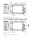
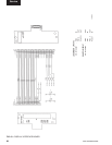
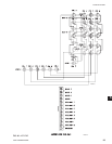
SHARP model LQ10D367 and LG Semicon LP104V2
display requires a TDK CXA-LO612-VJL Backlight
Inverter Board (YORK P/N 031-01789-000) (ref. Fig. 39
and Fig. 40). These boards generate a lamp illumination
high voltage AC from +12VDC. When the Backlight
Enable signal at connector CN1-3 is +5VDC, the high
voltage signal is applied to the lamp. When CN1-3 is
0VDC, the high voltage signal is removed from the lamp,
turning it off. The lamp brightness is controlled by a
variable voltage signal, developed by the lamp dimmer
circuit (ref. Fig. 34) on the Microboard and applied
to connector CN1-4. The lamp dimmer circuit varies
the voltage at CN1-4 over the range of 0 to +3.0VDC.
0VDC produces maximum (100%) brightness; +3.0VDC
produces minimum (0%) brightness. Voltages between
these values produce a linear brightness 0 and 100%.
Connector CN2 applies the high voltage lamp illumination
signal to the lamp.
5