


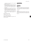
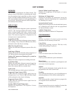
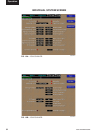
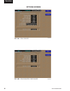
OVERVIEW
This screen is accessed from the Unit Screen. A chiller
can consist of separate refrigerant circuits. Each
refrigerant circuit is referred to as a system. This
screen shows system specic information for each of
the unit’s refrigerant systems. This information can
vary according to the type of chiller. Reference the
chiller’s Installation, Operation, Maintenance Manual
(IOM) for details.
DISPLAY ONLY
System Status
Displays this refrigerant systems operational status.
The messages displayed include running status, cooling
demand, fault status, external cycling device status,
load limiting, and antirecycle timer status. The status
message that is displayed on the Unit’s microprocessor
is represented here.
System Run (LED)
Displays this refrigerant systems operational status. Is
ON when the system is running.
Locked Out (LED)
Is ON when a system is locked out on a fault requiring
a manual reset at the chiller or condenser unit micro
panel.
System Run Time
Displays the amount of time the system has run.
Temperatures and pressures are either measured directly
by transducers and temperature sensors, or computed
from these measurements. Depending on the type of
chiller, the following temperatures and pressures could
be displayed:
• Discharge Pressure • Oil Pressure
• Suction Pressure • Oil Temperature
• Discharge Temperature • Suction Superheat
• Saturated Discharge Temperature
• Discharge Superheat
• Suction Temperature
• Saturated Suction Temperature
Motor Current (%FLA)
This displays the motor current of the system in percent
of full load amps.
Slide Valve Step (If screw)
This indicates the compressor slide valve step.
Compressors Running
(If more than one compressor per circuit)
Indicates the number of compressors running
Load Limit Stage
Indicates which stage of Load Limiting a unit is in.
Load Stage
Indicates the number of solenoids on the compressor of
a YCAR unit that are de-energized and loaded.
Condenser Fan Stage
Displays the stage of condenser fan operation on the
system.
Cooler Inlet Refrigerant temperature (Only if in
R-407c mode)
Displays the refrigerant temperature at the inlet of
the cooler.
Liquid Line Solenoid (LED)
Is ON when the Liquid Line Solenoid Valve is energized/
open.
Economizer Solenoid (LED)
Is ON when the economizer Thermal Expansion Valve
Solenoid is energized/open.
Oil Cooling Solenoid (LED)
Is ON when the Oil Cooling Solenoid Valve is energized/
open.
Compressor Heater (LED)
Is ON when the compressor heater is on.
Hot Gas Bypass (LED)
Is ON when the hot gas bypass valve is open.
PROGRAMMABLE
None
NAVIGATION
Home
Causes an instant return to the Home Screen.
Unit Data
Causes an instant return to the Unit Screen of the
selected unit.
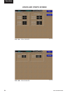
System #
A detailed view of the specied (#) system information.
SYSTEMS SCREEN
3