


FORM 50.40-OM2
69YORK INTERNATIONAL
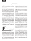
The DRAM (dynamic random access memory) is a
non battery-backed memory device. The Micro stores
data here temporarily for further processing. Data
in this device is lost during power failures. DRAM
differs from RAM in that DRAM must be periodically
refreshed in circuit.
The BIOS EPROM (basic input/output system erasable
programmable read only memory) is a memory device
that contains the bootstrap or power-up program. It
is located in socket location U45. This EPROM is
replaceable. Refer to the YORK Renewal Parts List.
The EPROM version is an alphanumeric code that
represents the application and revision level. The
version is printed on a label adhered to the EPROM’s
surface. The version code is as follows:
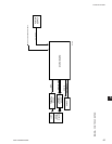
When power is applied to the Control Center following
a power failure, the Micro executes the instructions
in the BIOS EPROM program to initialize, congure
and start operation of certain Microboard components
before the main program (stored in the Flash Memory
Card) is started. Depending upon the application, the
Microboard could be equipped with an EPROM that
has either 128K, 256K or 512K capacity. Microboard
Program Jumper JP38 must be positioned according to
the actual EPROM installed. Refer to Table 2 (Program
Jumpers). There are 5 steps to the boot-up process.
During the boot-up process, there is a visual indication
as each step is performed, followed by a Pass/Fail
status of the step. On the Microboard, a green LED
ashes to indicate the step was successful. If a step
is unsuccessful, a red LED ashes and the Boot-up
process terminates. The execution and Pass/Fail status
of steps 3 through 5 are displayed on a white Keypad
Display Screen as they are performed. This white
display screen also lists the BIOS EPROM Version.
The steps of the Boot-up process are as follows. Also,
below is listed the LED activity associated with each
step.
BOOT-UP STEP AND DESCRIPTION
1. First initiate table complete.
Registers in the Micro are congured to allow it to
perform basic memory read/write functions.
2. FPGA conguration.
The Field Programmable Gate Array (FPGA) is
congured to process Digital Inputs and Outputs.
3. Mini-card signature test.
A location in the Flash Memory Card that contains
a code identifying the Manufacturer is compared to
other locations that contain the manufacturer’s name.
If these values are the same, it is pass. If they are
different, it is fail.
4. Mini-card checksum.
The Flash Memory Card checksum is calculated and
compared to the checksum value that is stored in the
Card at the time the Card was initially programmed
at the YORK factory. If both values are the same, it is
considered pass. If the calculated value is different than
the stored value, it is considered fail.
5. BRAM quick test.
Test data is written to and then read from several
memory locations to verify BRAM operation.
LED INDICATORS
When power is applied to the Control Center, both
the red and green LED’s simultaneously illuminate
for 1 second, then the Boot-up process begins in the
following sequence (Note: While one LED ashes the
other is off.). When all steps have been completed, both
the green and the red LED’s illuminate and remain
illuminated.
STEP PASS FAIL
1 Green on, Red off
Watchdog will
initiate a re-boot.
2 Green ash once
Boot-up process halts.
One red ash repeating
3 Green ash once
Boot-up process halts.
Two red ashes repeating
4 Green ash once
Boot-up process halts.
Three red ashes repeating
5 Green ash once
Boot-up process halts.
Four red ashes repeating
C. MLM. 00. XX.
Revision level. Increments 01, 02 etc.
OptiView BIOS EPROM
MILLENNIUM
Commercial
5