


YORK INTERNATIONAL10
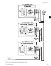
• At the chiller/condenser control panel that uses
a rotary switch to set the ID, use a small screw
driver to rotate the rotary switch so that the arrow
points at the number that coincides with the Unit’s
Identication number (ID#). Unit 1 - Unit 8 coincide
to rotary switches 0 - 7. Otherwise program the
panel’s ID through keypad entry.
Never skip an ID#. For example, if
you have four units then they must be
identied from ID#0 - ID#3.
• At the chiller/condenser unit’s control panel, select
the type of control mode. Select REMOTE only if
remote control is desired. Select LOCAL to only
monitor this unit.
• From the Comms Screen of the OptiView RCC,
enter the RCC Poll Time. This is how often (time
in seconds) to request data. This time should be set
long enough to allow for receiving the data.
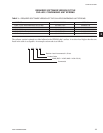
WIRING
A communications cable must connect the chiller to the
remote panel. This cable should be a three-conductor
with foil shield and drain wire, 20 awg or larger sized
wire, 300v, 80 Deg. C, U.L. Style 2464, U.L. listed
and CSA approved. Three sources are Alpha 5463,
Belden 9364, or Quabbin 0220. The cable length (sum
of lengths of all cables) must not exceed 4000 ft.
(1219 m.).
Never run the communication cable in
close proximity to any power wiring.
For best results, it should be run in
dedicated, grounded conduit. See
Proper Installation Practices.
SECTION 2 – INSTALLATION
MOUNTING
Mount the Remote Control Center at a level that
provides for easy viewing of the color graphic display
by all users. Securely mount it at the desired location.
The panel may be mounted away from the chiller as far
as 4000 ft. (1219 m.) of wiring will allow.
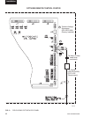
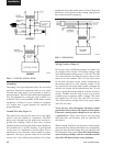
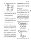
INSTALLATION CHECKLIST
(Reference Fig. 2 for wiring)
• A communications cable must connect the OptiView
RCC to the chiller/condenser control panel. This
cable should be a three-conductor with foil shield
and drain wire, 20 awg or larger wire, 300v, 80 Deg.
C, UL Style 2464, UL listed and CSA approved.
Three sources are Alpha 5463, Belden 9364, or
Quabbin 0220. The cable length (sum of lengths of
all cables) must not exceed 4000 ft. (1219 m.). The
cable is user supplied.
• Obtain ferrite (part number 025-35154-000) from
the cloth bag found in the OptiView RCC and
install it as shown on Fig. 2. This must be installed
to meet FCC and CE requirements.
• Make sure that the Transient Voltage Suppressors are
installed at J12. One is installed from “+” to “GND”
and one is installed from “-” to “GND”.
• At J12 of the OptiView RCC, red wire on RS485(+),
black wire on RS485(-) and white wire on Ground.
• At the OptiView RCC, connect the shield to the
panel.
• Use a tie wrap between the J12 connector and the
Ferrite (part number 025-35154-000) to secure the
shielded cable to the OptiView RCC. The tie wrap
can help prevent the wires from being accidentally
pulled out of the J12 connector by someone working
in the panel or by the weight of the ferrite.
• Install a LAN transient protection module at the
chiller/condenser control panel and connect the
cable according to the type of control panel.
• Make sure the correct EPROM is installed at the
chiller/condenser control panel(s). See Table 1.
• From the Setpoints Screen of the OptiView RCC,
enter the Number of Units Connected (Maximum
value allowed is 8).
Installation