


FORM 50.40-OM2
15YORK INTERNATIONAL
There can be electrical circuitry that
presents an electrocution hazard. Be
sure that the sources of all power
supplies have been properly isolated
and secured before attempting any
service related activities.
External wiring, unless specied as
an optional connection in the manu-
facturer’s product line, is not to be
connected inside the OptiView Remote
Control Center cabinet. Devices such
as relays, switches, transducers and
controls may not be installed inside
the OptiView Remote Control Center.
No external wiring is allowed to be
run through the OptiView Remote
Control Center. All wiring must be in
accordance with YORK’s published
specications and must be performed
only by qualified YORK personnel.
YORK will not be responsible for
damages/problems resulting from
improper connections to the controls
or application of improper control
signals. Failure to follow this will
void the manufacturer’s warranty and
cause serious damage to property or
injury to persons.
PROPER INSTALLATION PRACTICES
Earlier relay systems were virtually immune to radio
frequency interference (RFI), electromagnetic interfer-
ence (EMI), and ground loop currents. Installation
consisted of hooking up the point-to-point wiring and
sizing the wire properly.
In an electronic system, improper installation will
cause problems that outweigh the benets of electronic
control. Electronic equipment is susceptible to RFI,
EMI, and ground loop currents which can cause equip-
ment shutdowns, processor memory and program loss,
erratic behavior, and false readings. Manufacturers of
industrial electronic equipment take into consideration
the effects of RFI, EMI, and ground loop currents and
incorporate protection of the electronics in their designs.
These manufacturers require that certain installation
precautions be taken to protect the electronics from
these effects. All electronic equipment must be viewed
as sensitive instrumentation and therefore requires
careful attention to proper installation procedures.
There are a few basics, that if followed, will result in
a trouble-free installation. The National Electric Code
(N.E.C.) is a guideline for safe wiring practices, but
it does not deal with procedures used for electronic
control installation. Use the following procedures for
electronic equipment installation. These procedures are
to be used in conjunction with the N.E.C.
Wire Sizing
Size supply wires one size larger than required for
amperage draw to reduce instantaneous voltage dips
caused by large loads such as heaters, contactors
and solenoids. Sudden dips in voltage can cause the
processor to momentarily malfunction or cause a
complete reset of the control system. If the wire is
loaded to its maximum capacity, the voltage dips are
much larger, and the potential for a malfunction is
very high. If the wire is sized one size larger than
required, the voltage dips are smaller than in a fully
loaded supply wire, and the potential for malfunction
is much lower.
The NEC code requires specic wire sizes to be used
based on current draw. An example would be to use
#14 gauge wire for circuits up to 15 amp or #12 gauge
wire for circuits of up to 20 amp. Therefore, when
connecting the power feed circuit to an electronic
industrial control, use #12 gauge wire for a maximum
current draw of 15 amp and #10 wire for a maximum
current draw of 20 amp.
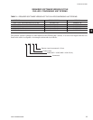
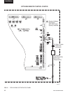
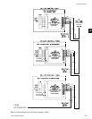
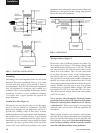
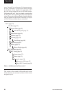
Voltage Source (Figure 3)
Selecting the voltage source is extremely important
for proper operation of electronic equipment in
an industrial environment. Standard procedure for
electronic instrumentation is to provide a “clean”
separate source voltage in order to prevent EMI, from
other equipment in the plant, from interfering with
the operation of the electronic equipment. Connecting
electronic equipment to a breaker panel (also known as
lighting panels and fuse panels) subjects the electronic
equipment to noise generated by other devices con-
nected to the breaker panel. This noise is known as
electromagnetic interference (EMI). EMI ows on
the wires that are common to a circuit. EMI cannot
travel easily through transformers and therefore can
be isolated from selected circuits. Use a control
transformer to isolate the electronic control panel from
other equipment in the plant that generate EMI.
2