


FORM 50.40-OM2
87YORK INTERNATIONAL
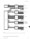
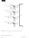
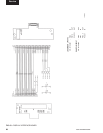
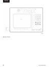
DISPLAY INTERFACE BOARD
(REFER TO FIG. 43)
The Display Interface Board is located on the Liquid
Crystal Display mounting plate and is part of the
Microboard interface to the Display. It permits the use
of Displays by different manufacturers, by providing the
Microboard with a means of automatically determining
which Display is present.
Since different Display manufacturers require different
timing and control signals, the Display Controller on the
Microboard must be congured to meet the requirements
of the actual Display installed. When AC power is
applied to the OptiView Remote Control Center, as part
of the power-up sequence, the Microboard reads the
four Panel ID wire jumpers, PID0 through PID3, on the
Display Interface Board to determine which Display is
present. The conguration of these jumpers indicates the
actual Display that is installed on the OptiView Remote
Control Center door. The Display Controller on the
Microboard is then congured appropriately.
On Sharp displays the conguration of wire jumpers
P30 and P31 determines whether the Display scan
orientation is Normal or Reverse (image reversal) scan.
As described in the preceding “Display” description,
Normal scan is left to right, beginning with the top row
and continuing sequentially through the rows to the
bottom row. Normal scan is used in OptiView Remote
Control Center applications. In Display applications
other than OptiView RCC applications, image reversal
is sometimes required. In image reversal applications,
the scan is reversed; the scan is right to left, beginning
with the bottom row and proceeding to the top row.
The jumper congurations determine the voltage level
at Display Interface Board J1-30 (P30) and J1-31
(P31). If P30 is IN, the voltage at J1-30 is +5.0VDC or
+3.3VDC (as determined by position of Microboard
Program Jumper JP2); if OUT, 0VDC. If P31 is IN,
the voltage at J1-31 is GND; if OUT, 0VDC. The
Display reads these voltages and adopts a scan mode
as follows:
SHARP LQ10D367 & LQ10D421 Displays:
SHARP displays require conguration of both jumpers
to achieve total image reversal.
P30 IN - Normal scan; left to right
OUT - Reverse scan: right to left
P31 IN - Normal scan; top to bottom
OUT - Reverse scan; bottom to top
The wire jumpers on this board are not eld congu-
rable, as with typical Program Jumpers. There are two
variations of the Display Interface Board. Each board
has the wire jumpers congured appropriately for the
display to which it is attached, as shown below. Display
Interface Boards are available individually for service
replacement. The YORK part number of the Display
Interface Board compatible with the installed Display is
listed on a label attached to the Display mounting plate.
However, service replacement Displays are provided
as a kit (331-02053-000) that includes, among other
items, the appropriate Display Interface Board for
the Display included in the kit. Refer to explanation in
“Liquid Crystal Display” description.
031-01765-001:
Display applicability - LG Semicon LP104V2
Jumper conguration - PID0 - IN
PID1 - OUT
PID2 - OUT
PID3 - OUT
P30 - OUT
P31 - OUT
031-01765-002:
Display applicability - SHARP LQ10D367
Jumper conguration - PID0 - OUT
PID1 - IN
PID2 - OUT
PID3 - OUT
P30 - IN
P31 - IN
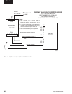
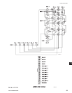
The red, green and blue display drive and control signals
are simply passed through the Display Interface Board.
The value of VCC is either +5VDC or +3.3VDC,
as determined by the position of Program Jumper
JP2 on the Microboard. PID0 through PID3, when
installed, connect their respective Microboard (J5)
inputs to GND; when removed, the Microboard pulls
these signals up to +5VDC. When P30 is installed, the
Display input (CN1-30) is connected to VCC (+5VDC
or +3.3VDC as determined by Microboard Program
Jumper JP2). When P31 is installed, the Display input
(CN1-31) is connected to GND.
5