


84
Power
source
AC100V
L
N
L
N
24V
GND
E
Circuit
breaker
for main
power
source
Arrestor
for main
power
source
Circuit
breaker
for PLC
Insulating
transformer
Power source
unit (Q61P-A1)
CPU unit
(QO2CPU)
Ethernet unit
(QJ71E71-100)
10BASE-T
DC input unit
(QX40)
G-50A
PC for
centralized
control
Circuit
breaker
for DC
power
source
DC24V
Power
source
Arrestor
Arrestor
Arrestor
Arrestor
Storage panel
for PLC
CPEVS f0.9-1P
or
CVVS1.25mm
2
Terminal for
pulse input
Terminal for
pulse input
Terminal for
pulse input
Terminal for
pulse input
Voltmeter
with pulse
oscillator
Voltmeter
with pulse
oscillator
Voltmeter
with pulse
oscillator
Voltmeter
with pulse
oscillator
Storage panel
for voltmeter
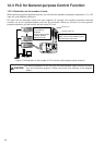
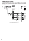
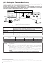
Figure 12-7 Wiring example around PLC
12.6 PLC Wiring Diagram
A wiring example around PLC is shown in Figure 12-7. In the figure below are shown also necessary
components in order to secure reliability (for reference). Depending on the setting environment, however,
unnecessary components may be included. In this case, consult with a contractor to decide whether or not
they are necessary.