74
11.1 Outline
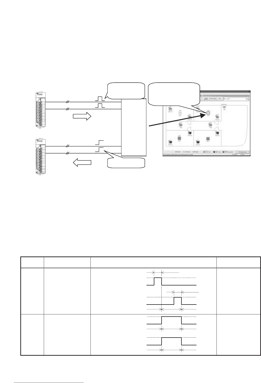
PLC will be used to control general-purpose equipment, along with a DI board (DC input unit) and a DO
board (transistor output unit).
One icon will be shown on the TG-2000A monitor screen to represent one system equipment, and you can
operate (one shot pulse output), monitor the status, and monitor for error (level input).
Therefore, you will be using two terminals on DO board and two terminals on DI board for one system
equipment.
For status monitoring, you can choose the name of the status, and for error status, you can choose the
name of the error and its icon color.
11.2 System Design Method
System design method for general-purpose control is outlined below.
11.2.1 Listing up of general-purpose equipment
General-purpose equipment needs to be listed up.
Control and monitoring of general-purpose equipment will be done through contact control using PLC.
Therefore, the equipment to be controlled should have the following signal specifications. TG-2000A can
only operate or only monitor the equipment, in that case, unused terminals should remain unconnected.
Table 11-1 General-purpose control signal specifications
Operation
Monitoring
Signal specifications
Non-voltage a-contact
One shot pulse output
Non-voltage level input
Terminal assignment/
equipment
1
2 terminals
2 terminals
Contact specifications
Signal 1 (operate)
approx. 1 second
approx. 1 second
Contact ON
Contact OFF
Contact ON
Contact OFF
Signal 2 (stop)
Signal 1
Contact ON
Contact OFF
Contact ON
Contact OFF
Signal 2
Stop Run Stop
Stop Run Stop
Normal
Error/trouble
Normal
Run
Stop
1P
1P
System
equipment 1
PLC DO board (QY40P)
PLC DI board (QX40)
One shot pulse
output signal
You can control and
monitor one system
equipment with one icon.
Level input signal
Control
Operation status
Error status
1P
1P
Monitoring
Figure 11-2 General-purpose control outline
1
Number of terminals assigned to one system equipment


