15
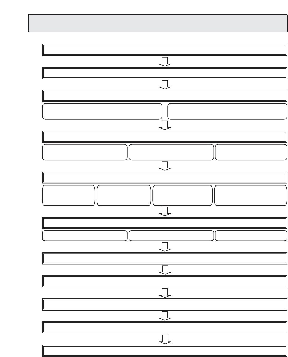
Step-1: Selection of air conditioning equipment (Objective equipment for control, limitations and the like)
Step-2: Selection of system control parts (Quantity of G-50A and other system controllers)
Step-3: Construction of G-50A system (Limitation on LAN wiring and the like)
Step 4: Optional function (With weekly/annual schedule employed)
Step 5: Optional function (With electric power apportioned charging)
Step 6: Optional functions (energy saving function, demand control function)
System 1: With centralized control by PC employed
(Connection of plural G-50A unit)
System 1: Applied weekly/annual schedule
by integrated software
System 2: Applied weekly/annual schedule
by Web monitoring
System 3: Annual schedule not
applied
Step 7: Selection of measuring instruments
Step 8: General purpose equipment control
Step 9: Determining number of PLC units
Step 10: Determination of address for air conditioning equipment and PC for control
Step 11: Confirmation of other functions
System 1: Energy saving control System 2: Peak cut control System 3: Not applied
System 1: Electric power
pulse counting
System 2: Electric power
manual inputting
System 3:
Measuring instrument
(Direct reading
method)
System 4: Electric power count by PC
direct connect (Watt Hour
Meter (RS-485))
System 2: Without centralized control by PC employed
3. System Design Flow
The design flow to construct the G-50A system is given below.


