


70
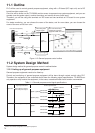
9.4 Energy Saving Control System Design Flow
Following is the outline of the system design flow for energy saving control execution.
(1) Determine the license type.
If you try to have a peak cut control by calculating power consumption from a watt-hour meter, you will
need to have a separate PLC (with a pulse count software installed). A peak cut control license will be
required for this.
If you do not implement a level control, you don’t need to arrange a PLC, or to decide a demand level. In
this case, you will need to have an energy saving control license.
If you do a peak cut control, you will set the Watt-hour meter in increments of G-50A. The control level
will be set at 5 steps. As a concept, you will consider the target contract demand based on the current
contract demand, and determine the value for the final level (Level 4). Then, you determine the figure at
each level leading up to Level 4.
[Example] Level 0: ~ 200 kW
Level 1: 200kW ~ 500 kW
Level 2: 500kW ~ 800 kW
Level 3: 800kW ~ 1000 kW
Level 4: 1000kW ~
(2) Select the energy saving control method.
As an energy saving control method, you choose either [energy saving control using indoor units] or
[energy saving control using outdoor units], or both.
[Example] Use both indoor unit energy saving control and outdoor unit energy saving control.
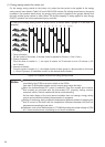
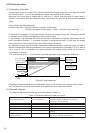
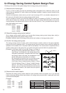
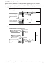
(3) Confirm the energy saving area.
The energy saving control of indoor units is done through a rotation control of the group operation
based on the unit of operation block. The energy saving control of outdoor units is done by rotating the
operation of the outdoor unit in numerical order of the address. The control order is sequenced from a
smaller number given to the group. First, you confirm the order of control within the operation block.
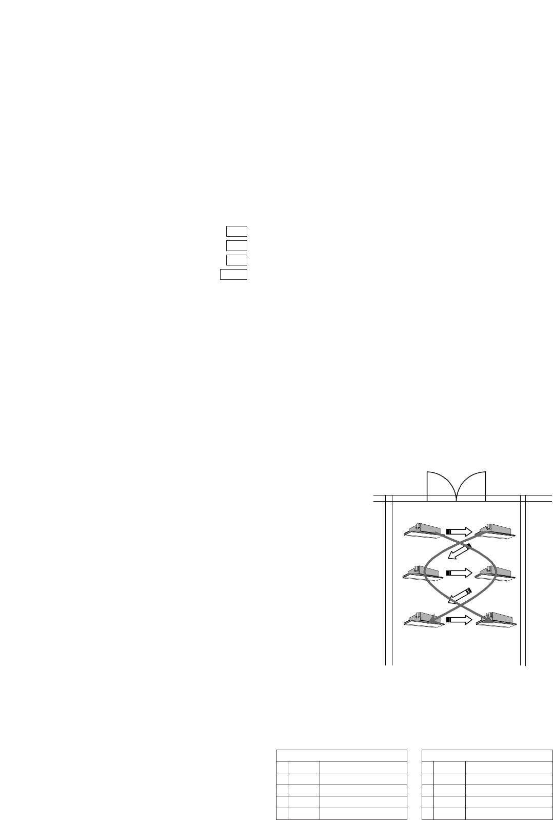
[Example] In the figure shown on the right, Group 1 to Group 6
belong to the same operation block (Office A). In this
case, Group 1 and Group 2 on the window side will be
controlled consecutively. Compared with the Group 5
and Group 6 side of the room, the temperature in the
window side goes up temporarily (in summer).
By rearranging the groups you can provide energy
saving control without too much sacrificing comfort.
In this case, Group 4 should become Group 2, Group
5 should become Group 3, Group 2 should become
Group 4, and Group 3 should become Group 5. By
doing so, you can avoid two window side units having
energy saving control at the same time and improve
the comfort level.
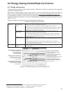
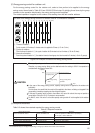
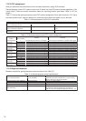
(4) Determine the control details.
Determine the energy saving control details for each operation block and outdoor unit. If you set both
indoor unit energy saving control and outdoor unit energy saving control within a particular level, both
controls will be multiplied.
[Example]
Level
Level 4 1000 ~ kW
Level 3 800 ~ 1000 kW
Level 2 500 ~ 800 kW
Level 1 200 ~ 500 kW
Level 0 ~ 200 kW
Office A
Group 1 Group 2
Outdoor
Group 5 Group 6
Group 3 Group 4
Office A
30
9
6
3
3
minutes
minutes
minutes
minutes
minutes
Stop
Fan control
Fan control
Fan control
Temperature control
Outdoor Unit 51
–
30
30
30
–
minutes
minutes
minutes
minutes
minutes
None
Capacity saving 60%
Capacity saving 70%
Capacity saving 90%
None