


5. Explanation of Devices
5.3 Detailed Explanation of Devices
- 77 -
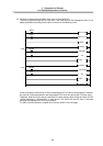
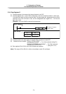
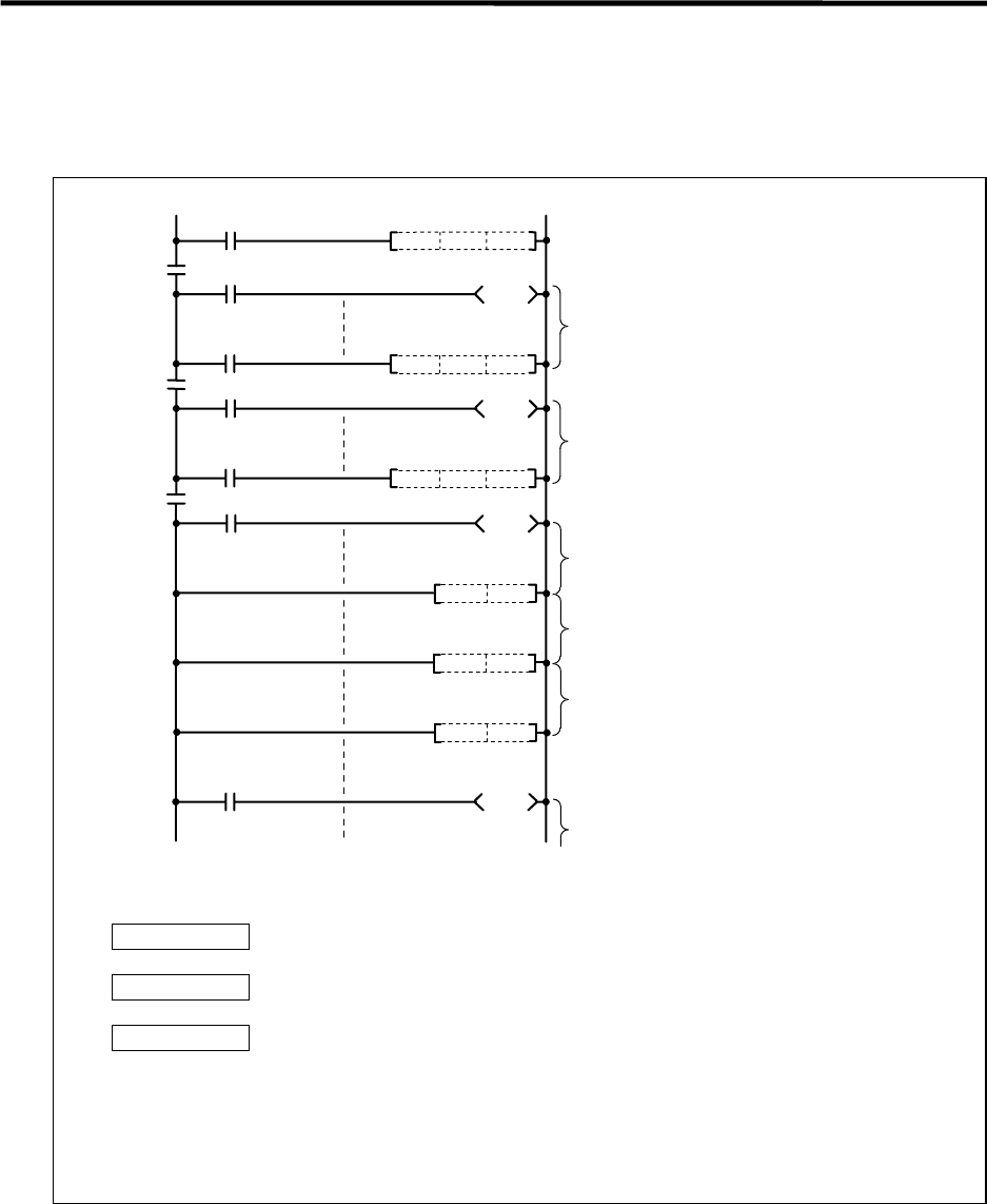
5.3.12 Nesting N
(1) This indicates the master control nesting structure.
(2) The master control nesting (N) is used in order from smallest number.
MC N0 M15
MC N1 M16
MC N2 M17
MCR N2
MCR
N1
MCR
N0
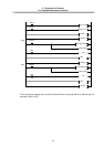
A
B
C
M15
M16
M17
N0
N1
N2
Execute when A conditions are set.
Execute when A,B conditions are set.
Execute when A,B,C conditions are set.
Reset MC2 to 7
Execute when A,B conditions are set.
Reset MC1 to 7
Execute when A conditions are set.
Reset MC0 to 7
Execute regardless of A,B,C conditions.
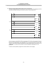
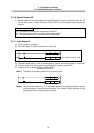
(a) The conditions for each master control to turn ON are as follow.
MC N0 M15 .......... ON when condition A is ON
MC N0 M16 .......... ON when conditions A, B are ON
MC N0 M17 .......... ON when conditions A, B, C are ON
(b) The timer and counter when the master control is OFF is as follows.
· 100ms timer, 10ms timer: The count value is set to 0.
· 100ms integrated timer : The current count value is retained.
· Counter : The current counter value is retained.
· OUT command : All turn OFF.
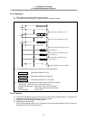
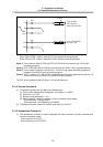
5.3.13 Pointer P
(1) The pointer indicates the branch command (CJ, JMP, CALL) jump destination. The pointer No.
assigned at the jump destination head is called the label.
(2) Pointers P0 to P249 are user release pointers.
(3) P255 always indicates END.
(P255 can be used as a device for CJ command, etc, but cannot be used as a label. This cannot
be used for the CALL command device.)