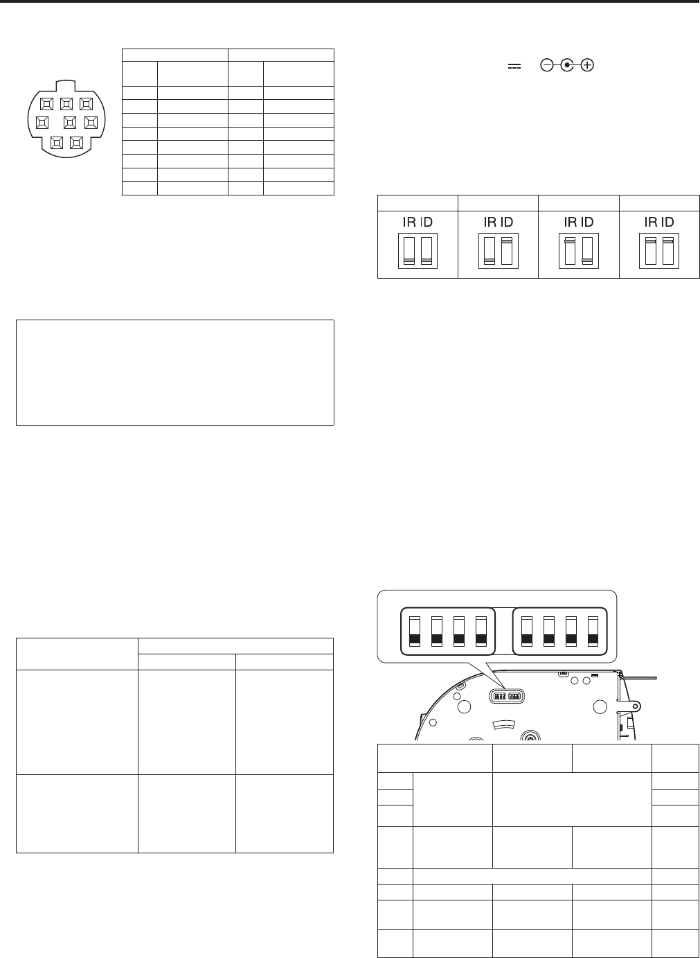
10. RS-232C connectors <RS-232C IN/OUT>
ConnectstoanRS-232Ccable.
RS-232CIN/OUT
connectorappearance
12
345
6
7
8
MiniDin8-pin(JST)
RS-232C IN RS-232C OUT
Pin
No.
Signal
Pin
No.
Signal
1 DTR_IN 1 DTR_OUT
2 DSR_IN 2 DSR_OUT
3 TXD_IN 3 TXD_OUT
4 GND 4 GND
5 RXD_IN 5 RXD_OUT
6 GND 6 GND
7 IROUTR 7 NC
8 IROUTL 8 NC
<NOTE>
•Beawarethatthepolarities(+/-)oftheserialdatamaybedifferent
dependingonthespecificationsofthedevicetobeconnected.
11. LAN connector for IP control <LINK/ACT>
ThisLANconnector(RJ45)isconnectedwhenexercisingIPcontrol
overtheunitfromanexternaldevice.Useacablewiththefollowing
specificationsfortheconnectiontothisconnector.
When using a PoE+ Ethernet hub
LANcable
*
1
(category5eorabove,straightcable),max.100
m[3280ft]
When not using a PoE+ Ethernet hub
LANcable
*
1
(category5orabove,straightcable),max.100m
[3280ft]
*
1
UseofanSTP(shieldedtwistedpair)cableisrecommended.
12. HDMI connector [HDMI]
ThisistheHDMIvideooutputconnector.
13. Anti-theft wire mounting hole
Theanti-theftwirebracket(availablefromahardwarestore)is
attachedhere.
14. G/L IN connector <G/L IN>
Thisistheexternalsyncsignalinputconnector.
ThisunitsupportsBBS(BlackBurstSync)andtri-level
synchronization.
Supplytothisconnectorthesignalsthatcorrespondtothevideo
signalformatwhichhasbeenset.
Format
External sync signal input format
BBS Tri-level sync
1080/59.94p
1080/29.97p
1080/23.98p
1080/59.94i
1080/29.97PsF
1080/23.98PsF
720/59.94p
480/59.94p(i)
480/59.94i
480/59.94i
480/59.94i
480/59.94i
1080/59.94i
1080/59.94i
720/59.94p
—
1080/50p
1080/25p
1080/50i
1080/25PsF
720/50p
576/50p(i)
576/50i
576/50i
576/50i
576/50i
1080/50i
1080/50i
720/50p
―
<NOTE>
•LockingtoasubcarrierisnotpossiblewithBBS.
15. VIDEO OUT connector <VIDEO OUT>
Thisistheoutputconnectorusedformonitoringthecamera’s
compositevideosignals.Usethemonitorintheinternal
synchronizationmode.
ProvideaBNCcoaxialcableastheconnectingcable.
ThereisadelayintheVIDEOOUTsignaloutputby120H(HDlines)
whenat720pandat90H(HDlines)foranyother.
16. Hole used to secure cable cover
Usethescrewprovidedtosecurethecablecover.
17. SDI OUT connector <SDI OUT>
ThisistheSDIvideosignaloutputconnector.
18. DC IN connector <12V IN >
ConnecttheACadaptorsuppliedwiththeunittothisconnectorto
supplytheDC12Vvoltagetotheunit.
19. Cable clamp
ThisisusedtoholdthecableconnectiontotheDCINconnectorand
preventitfrombecomingdisconnected.
20. IR ID switches <IR ID>
CAM1 CAM2 CAM3 CAM4
TheseareusedtoselecttheIDofthewirelessremotecontrol
(optionalaccessory).
TheIRIDswitchsettings“CAM1”to“CAM4”correspondtothe
<CAM1>to<CAM4>buttonsonthewirelessremotecontrol.
21. Square holes (X2) for cable cover tabs
Thetabsonthetwosidesofthecablecoverarefittedintothese
holes.
22. <AUDIO IN> connector
Inputsexternalaudio(microphone,line).
23. Ground connector
Connectstothegroundconnectoronawalloutlet,groundbar,etc.
forgrounding.(→page@@)
24. Tripod screw holes
(Screw: 1/4-20 UNC, ISO 1222 (6.35 mm))
Usethesescrewholeswhensecuringtheunittoatripod,etc.
25. Service switches
SW1
ON
OFF
SW2 SW3 SW4 SW5 SW6 SW7 SW8
Function OFF ON Factory
settings
SW1 Camera
addresssetting
(standardserial
communication)
SeedescriptionsforSW1toSW3 OFF
SW2 OFF
SW3 OFF
SW4 Communication
format
Panasonic
proprietaryserial
communication
Standardserial
communication
OFF
SW5 AlwaysleaveatOFF(usedforfactoryadjustments) OFF
SW6 Infraredoutput Disable Enable OFF
SW7 Communication
baudrate
9600bps 38400bps OFF
SW8 Communication
connector
RS-422 RS-232C OFF
<NOTE>
•Performswitchsettingsbeforeturningtheuniton.
•CameraswhosecameraaddresssettingswitchesaresettoAUTO
cannotcoexistwithcameraswhoseswitchesaresetto1to7.
•Manuallysettingmultiplecamerastothesameaddresswillnot
allowyoutocontrolmultiplecamerasfromasinglecontroller
simultaneously.
18 19
Parts and their functions (continued)


