


1
2
5
7
4
3
6
4
8
3
25
24
16 22 18
9 101321 15231417
11 12 2019 21
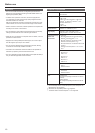
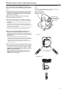
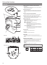
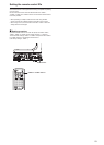
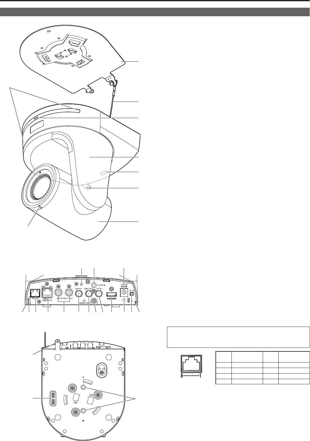
Rear panel
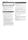
Bottom panel
1. Mount bracket for installation surface (supplied
accessory)
Mountthisbracketontotheinstallationsurface,andthenattachthe
cameramainunittothebracket.
2. Drop-prevention wire
Thiswireisscreweddowntothebottompanelofthecameramain
unit.Loopthecirclepartofthewirearoundthehookofthemount
bracket.
3. Hole for securing the camera pedestal
Thisholeisprovidedinthebottompanelofthecamerapedestal.
4. Wireless remote control signal light-sensing area
Thelight-sensingareaisprovidedinthreeplaces,onthefrontpanel
ofthecamerapedestalandatthetopoftherearpanel.
5. Status display lamp
Thislightsinthefollowingwaydependingonthestatusoftheunit.
Orange:Whenthestandbystatusisestablished
Green: Whenthepowerison
Red: Whentroublehasoccurredintheunit
Green and blinks twice:
WhenasignalmatchedbytheremotecontrolIDhas
beenreceivedfromthewirelessremotecontrol(optional
accessory)whilethepowerison
Orange and blinks twice:
WhenasignalnotmatchedbytheremotecontrolIDhas
beenreceivedfromthewirelessremotecontrol(optional
accessory)whilethepowerison
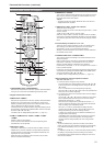
6. Camera head
Thisrotatesintheupanddowndirection.
7. Tilt head
Thisrotatesintherightandleftdirection.
8. Tally lamp
Thiscomesonorgoesoffinresponsetothecontrolfromthe
controllerbutonlywhen“On”hasbeenselectedasthetallylampuse
setting.
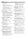
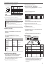
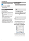
9. RS-422 connector [RS-422]
ThisRS-422connector(RJ45)isconnectedwhenexercisingserial
controlovertheunitfromanexternaldevice.Useacablewiththe
followingspecificationsfortheconnectiontothisconnector.
ThetallylampcanbelitbyshortingtheTALLYsignal(pin2)with
GND(pin1).
<NOTE>
•DonotapplyavoltagetotheTALLYsignalpin.
LANcable
*
(category5orabove,straightcable),max.1000m
[3280ft]
*
:
Use of an STP (shielded twisted pair) cable is recommended.
Pin
No.
Signal
Pin
No.
Signal
1 GND 5 TXD+
2 TALLY 6 RXD+
3 RXD– 7 —
4 TXD– 8 —
Parts and their functions
Camera unit
18
19